
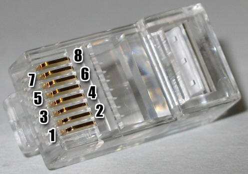
The Popeye is a power distribution system for your numerous, lower current devices scattered about the lab. Power is distributed over surplus phone and Ethernet cables (and the occasional 6-wire security camera cable). The design is simplicity itself; a number of RJ45 Ethernet female connectors are connected in parallel and many of the 8 pins are connected to a multiple voltage power supply. Here's the RJ45 pinout (public domain image from Wikipedia - thanks!) and my pin assignments:
 |
Pin # |
Function |
Typical Color |
| 1 | Ground (Zero Volts) | Orange/White | |
| 2 | Adjustable Voltage | Orange | |
| 3 | +5 VDC | Green/White | |
| 4 | +15 VDC | Blue | |
| 5 | Ground (Zero Volts) | Blue/White | |
| 6 | -15 VDC | Green | |
| 7 | Not Committed | Brown/White | |
| 8 | Not Committed | Brown |
It turns out that a four wire phone connector will plug into a RJ45 jack so I chose the center two wires to supply ground and +15 volts. Single line (two wire) phone cables are thus able to supply 15 volts to your project. The second pair (pins 3 and 6) add +5 and -15 volts so a two-line (four wire) cable will give all three voltages and a ground. For more complex purposes the additional pins may be employed by using an 8-conductor network cable. I've added another ground for good measure at pin 1 and dedicated pin 2 to a variable voltage, either an adjustable power supply or just a variable voltage for tuning a varactor or other light load. (Grab a network cable and connect pins 4 and 6 across a 100k pot and connect the wiper to pin 2 - plug it in anywhere in the system and all the pin 2's have that variable voltage.) Pins 7 and 8 are left disconnected to allow for data and signals to be arbitrarily assigned as the current project requires. That brown/brown-white twisted pair (pins 7 and 8) may also carry a high-speed differential signal.
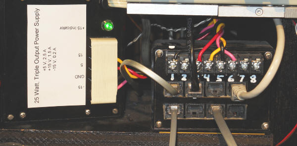
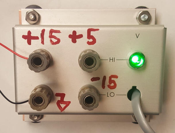
Here's one of my power "outlet boxes" tucked up under a shelf on my bench. I dragged the power supply out from the rear for the photo. Note the power supply connects via the screw terminals and one could connect additional voltages to the other screws. It's a two-way street; a signal or voltage could be coming in from your project on pin 7 and a wire could lead from that screw to a measurement instrument. Remember, every "pin 7" is hooked to every other, it's just an 8-wire bus. I've run separate wires across the room for a voltmeter only to remember I have the wire I need already in the cable!
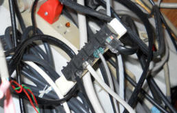
Over at one of my measurement computers I needed more "outlets" so I just added another one of the power strips by connecting a cable from the main power supply to the remote strip. Instantly, three more outlets were available:
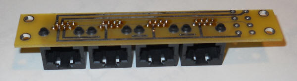
I made little boards that connect four female RJ45 connects in parallel. Sadly, the layout is lost but it's a straightforward concept. Doing it again I'd make the boards longer, sporting perhaps 8 connectors. Indicator LEDs wouldn't hurt either. Here are a handful of devices that use this system:
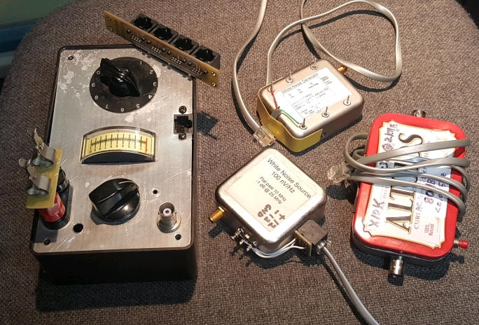
Note the big crystal tester has a built-in socket. (Nibbling from the edge makes a square hole easy!) One of the cans simply has the connector glued onto the side and the other has the wires soldered directly to the pins. Don't bother with those cheap phone cords with the copper ribbon wrapped around string; choose good cable with many strands of solid wire. The Altoids project uses +-15 volts, also with a dedicated cable. Below is a simple "outlet" box that provides remote 5-way binding post access to the three power supply voltages.
Watch out for "crossover" cables, both Ethernet and phone cables. Make sure the colors go to the same pins on both ends. If you are going to cut the cable in half (yielding two power cables, by the way) you can use both as long as you pay attention to the polarity. The connectors are quite inexpensive so you can just buy a tool and a bag of connectors and crimp on new connectors. The colors don't matter as long as they go to the same pins on both ends so you can make two new cables from a crossover cable.
Here's a related gadget you will like:
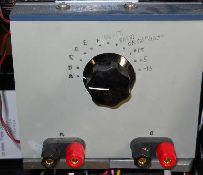
This is simply a two-pole, multi position switch, the output of which goes to my bench multimeter. The first two positions go to the two binding posts, the next four to bench supplies, the others to the +-15, +5 and variable voltage on the Popeye.
* Power Over Phone, Ethernet, Yada, Etcetera. I never was very good with acronyms. : )