
It is no accident that 'amour' and 'armour' have similar spellings!
Speak clearly to the Oracle, ask it any question, and it will
answer! You’ll get an answer, that’s for sure, but there’s no guarantee you’ll
get the right one!
This is a simple yet surprisingly entertaining little project which gives Yes/No
answers to spoken questions. The intention is that the answers are largely
random, but far too often the answer is consistently dependent on what is
spoken. I could have sworn at one stage it was a ‘Bee’/’Bah’ differentiator!
The circuit uses just one IC – a CD4049UBE unbuffered hex inverter. The first inverter is simply a linear amplifier to raise the signal level from a condenser microphone. The next two inverters form a hysteresis element (Schmitt trigger) which remembers the last large excursion (positive or negative) of the last utterance of the question. The fourth inverter is a simple buffer, and the last two inverters are timers which extinguish the LEDs while the question is being spoken.
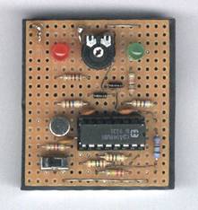
The circuit board in the picture was mounted onto the rear of a battery box to hold four ‘AAA’ batteries. A balance adjustment is provided which permits the relative frequency of ‘Yes’ and ‘No’ answers to be controlled a little, though some questions consistently give the same answer no matter what the balance setting (should I read something into that?!!!!!)
Remember – it’s a silly novelty so don’t get too spooked by it!
Happy oracles!
The USB revolution has brought huge benefits in terms of peripheral connectivity
but adds significant complexity to hobby activities that need a computer
interface. No more can we access raw signals through serial or parallel port
protocol lines. There is however one set of ports remaining that deal with
signals directly - the sound ports, specifically, 'line in', 'line out' and the
microphone socket.
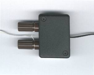
This project was inspired by a wish to create a simple computer interface for a
thermistor, and one that didn't need an additional power supply. The result is
my 'Mic Input Telemetry Interface', more commonly known as a 7555 low power
timer! The idea is to convert the thermistor resistance (in the range 5k to
50k) to an audio tone that the computer can sample and then measure.
Microphone inputs include a power supply in the form of a resistor connected to
a power rail in the PC, however, this appears far from standardised. My laptop
has a 4.7k resistor connected to a 3.2V supply, while my old Windows 98
computer has 1.5k connected to 2.5V. Sensitivity seems to vary too, my old
machine being significantly more sensitive than my laptop.
You can't draw much power from the microphone socket. It is enough to power the
FET preamplifier that's embedded in the case of electret microphones, but it was
never intended to power telemetry hardware. But it can - just!

The circuit provided produces a tone whose pitch varies with thermistor resistance. Note that no coupling of this tone to the microphone signal lead is required - the alternating current consumption of the IC produces enough supply ripple to provide an audio input. The actual signal seen on the microphone channel is a curvy triangle wave as shown in the plot below.
The 1uF capacitor serves to set the level of the audio (supply ripple) and was a
compromise for my two machines. I suspect it will be good for most PCs that are
around. If not, a lower value for this capacitor leads to a higher audio level,
and vice versa. Being a passive circuit there is probably little opportunity for
damaging the microphone input - unless the thermistor leads come into contact
with a voltage source of some kind.
If it is desired to position the thermistor remotely from the computer, then it
is probably best to extend the audio cable and place the circuit near to the
thermistor, as this will reduce the effect of cable capacitance on the
resistance/pitch linearity of the circuit.
Bear in mind that, if your thermistor is positioned outside of a building, it
presents a significant lightening hazard. At the very least this could damage
your computer in a lightning storm. At worst it could cause a fire or kill you!
Don't do it.
The 555 timer can probably be described as a 'semi-precision' component. This
circuit won't achieve high accuracy, but it can work quite well. A better
circuit is under consideration but will probably require an external power
source. It was relatively easy to create a Visual Basic application that samples
the microphone, measures tone pitch, and displays a reading on the screen:
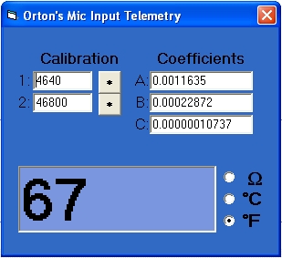
A two point calibration facility is included by which two known
resistance values (typically 4.7k and 47k) are substituted for the thermistor.
These two resistance values are entered into the '1' and '2' fields and the
associated buttons pressed when the resistors are connected and the application
has performed at least one reading update. Calibration data are stored in an
associated 'mictelem.dat' file, which the application creates in the same
directory as the program.
Calibration, then, permits the application to display resistance with at least a
little precision. Displaying temperature requires an additional mapping function
for the particular thermistor employed, and the formula used is the
'Steinhart-Hart' model which is expressed as follows:
Where:
T is absolute temperature in degrees Kelvin
R is thermistor resistance in Ohms
A, B and C are coefficients unique to the thermistor
The three coefficients A, B and C are determined for a particular thermistor by
taking three points in the thermistor characteristic (e.g. the ends and middle
of the range of interest) and solving simultaneous equations. An Excel
spreadsheet to do just that is included amongst the downloadable files. My
thermistor - the Fenwal 10k thermistor - is used as an example in the
spreadsheet, and the computed coefficients were transferred to my VB application
for use as default values for the user-settable coefficients.
If all works correctly, it will be possible to alter the display mode between
Ohms, degrees Centigrade and degrees Fahrenheit.
I have successfully used this circuit for measuring outside air temperature,
though I never leave it permanently plugged in (refer to the lightning hazard
mentioned earlier). I have also used it for more exotic purposes: Place an LDR
across the thermistor terminals, set your mixer so that the Mic input is routed
to your speakers and you have a light Theremin!
I have also used this interface as a Galvanic Skin Response meter, but I cannot
advise anybody to do that themselves. Anything that connects to the body must
have very good electrical isolation to ensure the safety of the 'patient'. This
circuit provides no isolation whatsoever and a failure of a component in your PC
might result in lethal currents and voltages getting to or through your body. So
don't use it for Galvanic Skin Response measurement!
This whole approach has caused me to think about programming a PIC to sample a
number of analogue and digital signals which it then encodes onto an audio
waveform. This audio waveform can then be captured and analysed by software to
extract the parameters for display or logging purposes. It is even possible to
transfer the signal by radio, leading to a new wireless technology Charles has
christened 'No Tooph'! But that's another project!
Here are the necessary files.
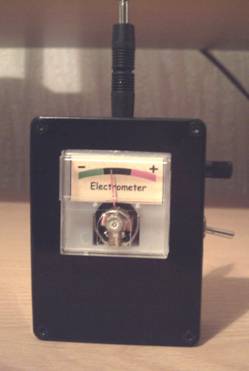
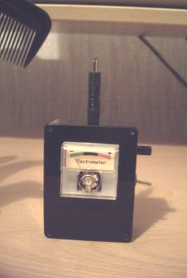
The following circuit is an electronic approximation of the ‘gold leaf electroscope’, except that this electrometer indicates polarity as well as electric field magnitude. It is incredibly sensitive! It will detect a television or an electrostatically charged comb from the other side of a room. It can even ‘see’ people moving about!
The neon bulb serves two purposes. It provides leakage at the FET gate and also helps to defend the FET against an electrostatic discharge. Do not omit the neon bulb – the FET won’t get the proper biasing without it. Ideally, the neon bulb should be in darkness, though the circuit seems to work okay with the neon bulb illuminated. The only effect is that the meter ‘autozero’ has a much shorter time constant when the neon bulb is illuminated.
The meter can be of the ‘VU’ variety though meters in the range 100μA to 1mA can be made to work. You may need to change the value of the adjustable resistor if a meter of widely different FSD to that specified is employed. A source of small, cheap meter movements is those cheap battery testers – their meters tend to be in the range 0.5mA to 1mA.
You won’t be able to walk around with this electrometer – the needle will just kick between its end stops if you try. Instead, it should be operated on a firm surface and left to settle for a minute or two. Adjustment of the ‘METER CENTRE’ adjustment is inevitably a trial and error affair, as bringing your hand near the electrometer will probably alter its reading.
The probe can be just a few inches of wire. The impressive looking probe on my meter is nothing more than a redundant adapter from an emergency mobile phone battery! I provided an earth connection through the body of the switch in anticipation that I might need to use my hand to remove excessive charge from the probe, but I haven’t actually needed to do that yet.
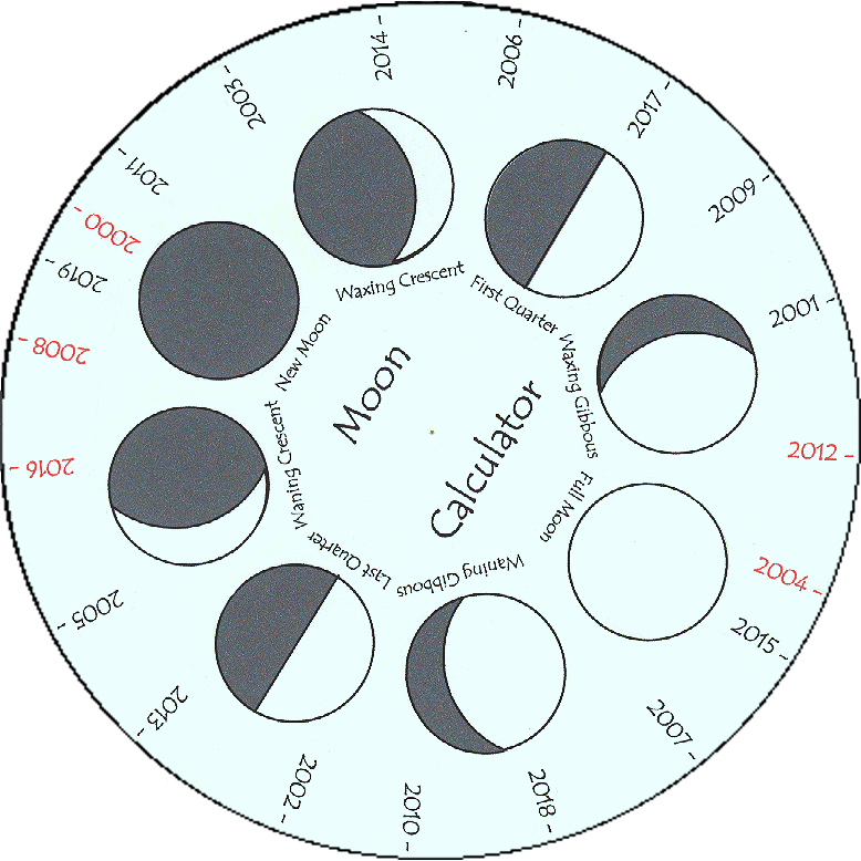
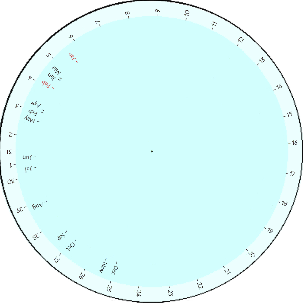
Print the following graphics, cut out the disks and pivot them with one of those brass fasteners (the sort with legs that you spread on the back). Line up the year with the month (red months for red leap years), find the date around the outside and voila! The moon phase at an instant!
What do you mean I have a moon fixation? Well, I probably have - I suspect
it's a feminine thing (Less of that!)
What is described here is a clock with a single hand that indicates the current moon
phase. It is based on a cheap clock as can be bought for less than a couple of dollars
(£1 in the UK). These clocks are powered by a single AA battery, and use a 32kHz 'tuning
fork' crystal as a timing reference. To convert your prosaic low cost clock into an Orton
Moon Clock requires the following steps:
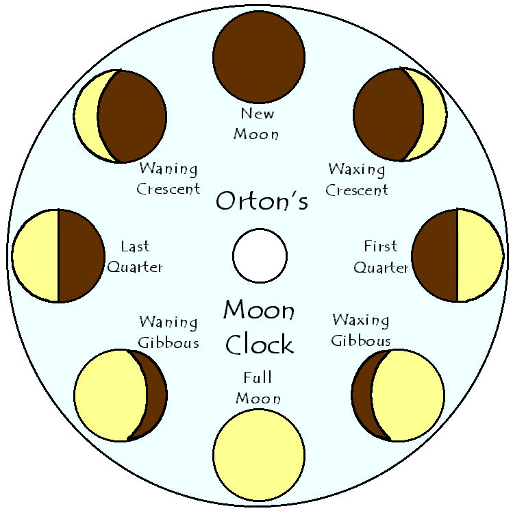
Firstly, all of the hands are removed, and the clock face is substituted with the Moon
Dial face shown in the graphic below. Only the hour hand is refitted to the central
cluster (but retain the second for the moment - it may prove useful later).
Next, the crystal is removed. Instead of the crystal, we are going to
drive the clock from a timebase of our own making, the purpose being to slow the clock
down by a factor of 59. Doing this results in the hour hand completing a revolution in
29.5 days - almost precisely the time taken for the moon to do one circuit around it's
phases! I have found this to be possible, at least on the clocks I have attacked (and they
are nothing out of the ordinary as these clocks go). The funny little motors in these
clocks don't seem to mind at all being driven many times slower than is normal.
Now, if you want a precision astronomical instrument, I recommend you build a crystal
timebase, using the crystal removed from the clock. A suitable CMOS circuit is
shown below.
If, however, you simply want a novelty that attracts curiosity at parties (not to mention a less than flattering reputation) then the much simpler timebase shown below will work.
Having removed the crystal, we inject our own timebase into one of the now open crystal
connections. But which? I probed the open terminals with a DVM. I found one to be close to
the negative supply, and the other close to mid-supply. I assumed the one at mid-supply
would be the input terminal to the oscillator. This proved to be wrong! My suggestion -
trial and error. If the second hand is re-attached, then you don't have to wait very long
to see evidence of the clock counting our timebase frequency - the second hand will
advance.
The second hand should advance every 59 seconds, and the 'Freq' preset in the simple
timebase should be adjusted until this is the case (if you are lucky enough to own a
frequency meter, then adjust for a frequency of 554.83Hz). Once set, the second hand can
be removed again, and the clock closed up before any of those tiny components fall out!
The alarm feature wasn't used on my clock. However, I can see the attraction of this
feature to lycanthropes the world over. It should still work fine, but the tone that the
clock produces is now so low that you will have to substitute a sub-woofer for the peizo
sounder.
Another approach seriously considered was to drive the clock even slower - using an
external timebase of 50Hz. If you do this, then the minute hand completes a revolution in
almost precisely the time the moon takes to complete it's orbital period (27.3 days). This
means that the face can have the zodiac around it's edge, and the minute hand will then
show where in the zodiac the moon is currently residing.
Note that this lunar 'orbital period' is not the same as the time taken for the moon to do
a complete circuit of it's phases. This is because when the moon has returned to the same
point on the zodiac, the sun has moved on about 30 degrees, and so the moon takes a little
longer to catch up (the moon's phase is dependent on the relative position of both the sun
and the moon).
It turns out that this 'catching up' effect is closely modeled by the same behavior of the
minute and hour hands. Driven from a 50Hz timebase, the hour hand completes a revolution
in very roughly a year. It's only about 11% accurate, this being down to the 12:1 gearing
of the clock fingers, when in fact there is a 13.38:1 ratio between the sun (earth) and
moon orbital periods. Had this been more accurate, then the hour hand could have been used
to indicate the sun's position in the zodiac. That would be nice. But it wasn't to be.
Despite the hour hand only roughly modeling the sun's motion through the zodiac, it turns
out that, as a means of obtaining the moon phase, the moon's phase can still be indicated
to an accuracy of better than 1%! This is accomplished by attaching the 'Moon dial'
graphic disc onto the hour hand. This disc rotates, thereby simulating the way the sun's
movement lengthens the moon's phase period over it's orbital period.
Anyway, enough of these crazy meanderings! I'm off now to make a clock which uses a
timebase with a division ratio of 3.36 x 10^12. This will create a clock which indicates
which geological time epoch you are in!
It's time for my pills now.
The I'Ching is an ancient Chinese method of divination based on 'trigrams'
- clusters of three complete or broken lines. Traditionally, obtaining a trigram involved
casting sticks and observing how they landed. Two trigrams would be obtained this way and
combined into a complete I'Ching reading or hexagram, which has six lines. This process
would be repeated, and the two hexagrams looked up in a 'Book of Changes' to reveal the
complete meaning of the reading.
Print and cut out the following rectangle, score along all lines, and then fold so that
same-numbered faces meet each other. There is no need to cut along any other line than the
rectangular outline - the internally folded faces will meet up precisely at the dice'
centre - all part of the magic of this unique octahedron!
The numbered faces could be glued, or simply held with double sided tape. When complete, you'll be able to throw a trigram. Read off your throw by looking at the uppermost surface, which will be level. Read so that the trigram line closest to the tip of the triangular face is seen as the topmost line. Throw twice to get a complete hexagram, or simply make two dice so that you can get your entire hexagram in one throw! Note how, when viewed at the right angle, the profile of this dice is square - another magical aspect of it's shape!
Make your living from your personality if you can. If you can't do that, make your living from selling your body. But if you are truly damned, make your living from your brain.