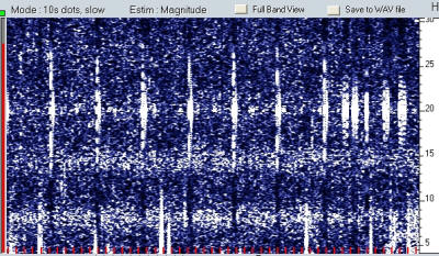
Using a similar circuit to the LF block converter, I've made a Schumann Resonance Converter that moves the near-DC signals up to around 2 kHz for an ordinary soundcard. Here's the maiden run plot:
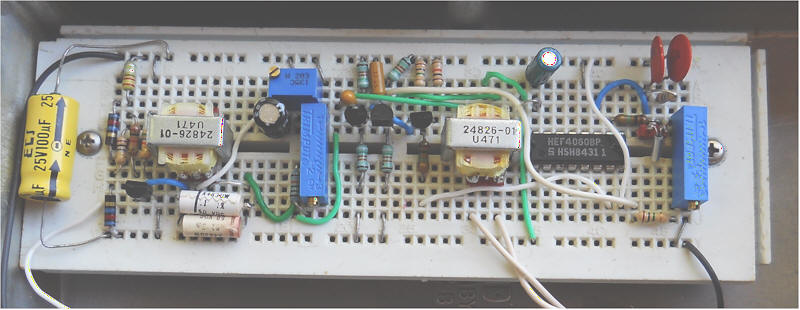
It seems to work! The fuzzy lines below 30 Hz are due to the Schumann Resonance. The image is from Spectrum Lab with an offset of 2.048 kHz (the L.O. frequency). The 60 Hz is reduced by an unusual bridged-T notch filter that uses a little audio transformer as the inductor. I discovered that the inductance of such a transformer can be varied quite a bit with a very tiny current (or even a weak magnet). Only 100 uA of DC current will tune the filter many 10's of Hz! Here's a snapshot of the schematic so far:
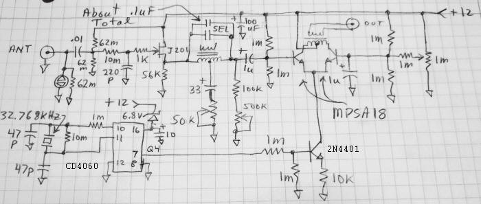
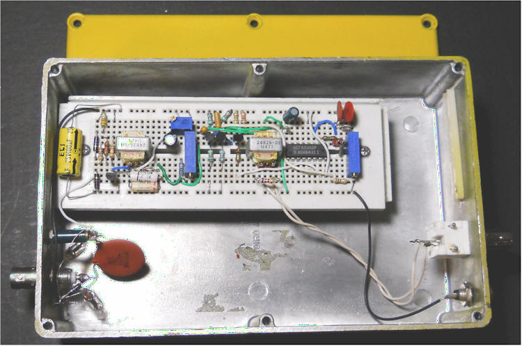
Circuit Description: Starting on the left, the antenna should be a fairly long vertical mounted high in the air, away from trees. The lead-in cable will have significant capacitance, perhaps as much as 1000 pF, and that's fine. (In fact, you might want to add a shunt capacitor if the hum is too big for the FET follower. If that's the case, you might also try increasing the 220 pF capacitor, to, say, 470 pF, but that's starting to eat into the gain at the higher Schumann resonance frequencies.) The first 62 megohm bleeds charge off the antenna and the neon bulb or other gas discharge device limits the voltage. Those components are on my RF connector, not in the photo. The .01 uF helps to isolate the JFET from the voltage and it should have a high breakdown voltage, just in case. The second pair of 62 megohm resistors bias the JFET gate to V/2, to give the source plenty of room to swing, since there's likely to be a big AC hum signal. Those big resistors could be comprised of 3, 22 megohms in series. The 10 megohm is in the signal path, but its noise is well below the atmospheric noise, and it works with the 220 pF to roll off the frequency response above about 70 Hz. The 1k is there to keep the JFET stable, regardless of the type chosen. The FET is very lightly biased by the 56k resistor and some current flowing in the transformer to conserve power for battery operation. The source of the JFET drives the bridged-T notch filter. The selected capacitor (indicated as two) resonates the transformer at 60 Hz, and the value will depend on the transformer; mine was about 0.11uf). The 50k pot sets the depth of the null and that value may require some experimentation with other transformers. The 500k pot and 100k resistor cause current to flow in the transformer, changing its inductance for tuning the center frequency. The differential amplifier performs the mixing, with the current sink transistor turning a small current on and off, about 200 uA (there should be a 2 volt square wave at 2 kHz on the 10k emitter resistor). The pot on the far right balances the two transistors so that they are turning on and off with equal duty-cycles, causing the 2 kHz to be canceled in the output transformer.
The two transformers are tiny 10k : 250 ohm (or something like that) types that I have in quantity. The winding ratio isn't important. It's a fairly low-Q set of values, and it might be interesting to try one of those telecom transformers that have about 10 H inductance. The required resonating capacitor will be significantly higher, near 1 uF.
I'm using the 20 dB microphone boost option in my soundcard menu and I selected a resistor to connect across the output to kill the gain a little. A shunt resistor across the output is a fine way to control the gain. Set the gain so that the time domain display has a large signal, but isn't clipping anywhere.
The total current drain is only 300 uA, so this can run on a lantern battery for years. Using a battery means the audio output transformer will completely isolate the grounds. It would probably run on a molded supply just fine.
The null potentiometer (on the right in the photo) is adjusted to minimize the carrier bleed-through at 2048 Hz. Try adjusting that for minimum signal on the time domain display with the input shorted.
Tuning the 60 Hz notch is tricky. My favorite way is to use a selective level meter tuned to 2108 Hz (2048 + 60) with a 20 Hz bandwidth, but you can also use Spectrum Lab with the spectrum scrolling pretty fast, say 300 mS. First adjust both pots to minimize the waveform on the time domain scope, then fine-tune both for minimum 60 Hz, Take your time; let the display settle between adjustments. You can get dips on the order of 30 dB or more, but it won't last as the line frequency wanders. The only purpose is to knock the 60 Hz down to avoid overloading the mixer stage, so a deep notch isn't necessary.
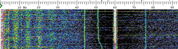
The low 2.048 kHz L.O. frequency means that Argo can view the results: