I recently purchased a large lot of old National Semiconductor ICs on eBay; I was interested in the JFET op-amps. In the lot were several MM5402N clock chips. When I was younger these clock chips were magical devices and I made quite a few clocks with them. These days the time of day is everywhere; even my phone can tell me the time, and that's time directly from time servers synced to national standards. Alas, my clock chips seem pretty obsolete, especially when one discovers they aren't even multiplexed. Yes, there's a separate wire for each display segment. But, if you like to solder, they're hard to beat! Here are a few projects using these old devices.
Ironically, my favorite use for these ICs doesn't even have a display! And add a divide-by-7 (typically a CD4526B) to the line frequency and it becomes a weekly reminder, turning on a lamp or other load for 7 hours once per week - great for an LED reminder for trash day!
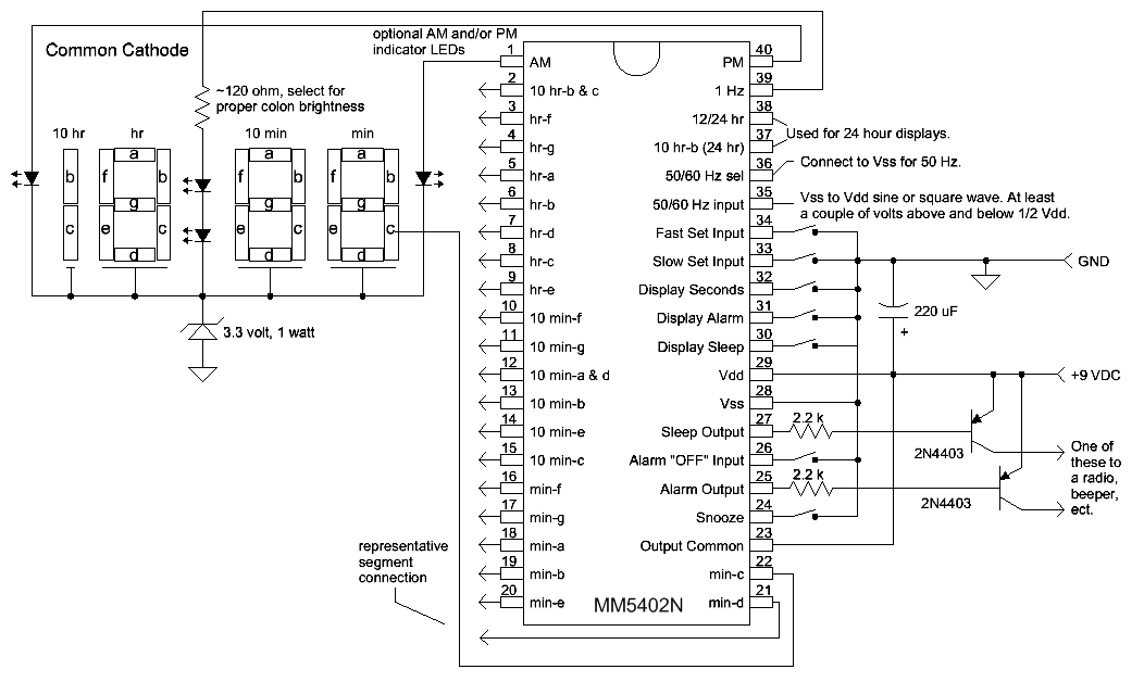
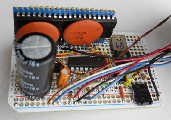
I studied the data sheet and came up with the following initial design (untested). The data sheet seems to imply that it's a good idea to burn off a few volts when using the common-cathode displays, hence the 3.3 volt zener diode. These ICs do have current limiting but when the maximum number of segments are lit, the chips can get pretty hot. The zener offloads some of that heat, keeping the IC within specifications. The ICs are rated to run on 7 to 11 VDC. That sounds like 9 volts to me.
This schematic doesn't show how to drive the 50/60 Hz input. Bias that pin up to 1/2 Vdd and apply a several volt signal at the desired line frequency through a capacitor, however you wish to come up with it. Use two, 1 megohm resistors and a 0.1 uF capacitor. Make sure Vp-p doesn't exceed Vdd. A peak-to-peak voltage of over 4 volts should be adequate so even a 5 volt CMOS logic signal should work if coupled as described. I really like the method I use on the display-free design below when using an AC power transformer; it gives a pretty good-looking "squarish" waveform with just the right amplitude for the IC.
I didn't really understand but it appears that the only difference between the "alarm" and "sleep" outputs is that the "sleep" output can be programmed to remain active for times less than 1 hour. I'd just use the alarm output!
When I began construction I discovered that I had common-anode displays so I came up with this:

I actually built an IC tester with a similar circuit but I used a somewhat different frequency reference than the one above. I haven't built the frequency source with the 74HC390s so there might be a mistake hiding in there. Just come up with either 50 or 60 Hz and a low duty-cycle pulse for driving the readouts. Note how I use an ordinary NPN transistor to square up the signal to be compatible with the IC.
It turns out that these ICs don't limit the current to a low enough value when sinking display current and it's important to use a limited duty-cycle voltage to power common-anode displays. You will find an application note on the web where the designer uses unfiltered AC and a "brightness" transistor to power the readouts in order to lower the chip dissipation. I used 40/60 duty-cycle but the IC still gets a little warm. There's a lower duty-cycle on one of the last '390's pins that would drop the power consumption quite a bit. Connect the 10k to pin 7 instead of pin 6 for a lower duty-cycle. It turns out that one wants a pretty dim display on a clock, anyway. Otherwise it's just too bright and you will throw a towel over it so you can sleep! If you really want the brighter display, make a heat sink for the IC like I eventually did:
That's a strip of 0.5" x 2" copper painted black and fastened to the top of the IC with metal oxide loaded epoxy. The chip runs far cooler with this heat sink, even when dissipating more power than the data sheet recommends. But, again, you really don't want a bright clock so just use a lower duty-cycle power pulse. You want to use pulses so that the current limit circuitry in the chip functions properly. Otherwise you might have uneven brightness.
But, you know what, who needs a digital clock anyway? Heck, practically everything I own has a clock in it. I even have a Radio Shack ballpoint pen with a clock in it! So, I came up with the ultimate application for these old ICs - the display-free alarm clock:
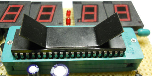
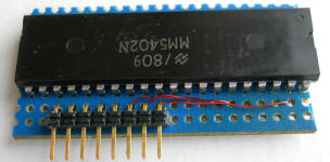
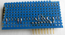
Look at all those unconnected pins! Leave off the "snooze" button and there's only 8 connections to the IC. Not wanting to use up all the holes on my Adafruit protoboard, I turned one of the ICs into a fairly tall "SIP" device: Now it uses only 8 holes.
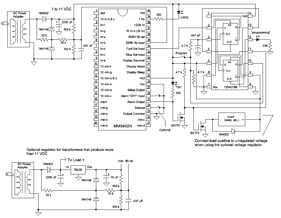
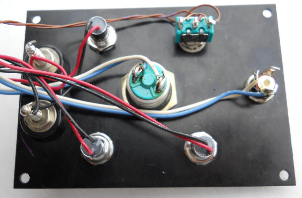
The indicated LEDs are optional. I ended up connecting the "On" LED right across the output terminals on my first unit since it supplies 5 volts. It's probably more useful to activate a relay to drive an AC load. The 1N4002 across the load is to prevent "kick-back" voltage if the load is a relay coil. Other loads, including solid-state relays, don't need that diode.
Imagine a box with a large pushbutton on top, a line cord, and a power outlet. One plugs in whatever appliance is desired and waits to press the button until the time of day when that appliance should turn on. Simply press the "program" button and the clock will program itself to turn on at that time of day, including the current day (after up to 24 seconds). It's quite an "organic" timer not requiring any "fussing" with displays and hard-to-remember programming routines. Just press the button when you want the thing to come on! I would add a button to turn the "alarm" off immediately to stop the function for today and maybe the "snooze" button to stop the function for 15 minutes (not as important). You can't "set" the thing the night before so it does take some "mental adjustment." But, really, most timer applications aren't that critical. I'm considering a device to turn on my garden soaker hoses for an hour every day, my emergency car battery jumper (which overcharges if left charging all the time), a porch light for the twilight hour when I sometimes come home, and on and on. These aren't critically timed events and being able to just hit a button to set the time is perfect. By the way, one can hit that program button at any time, even during the on-time hour and it will simply program to the current time. Here's how:
When you press the "program" button the bottom flip-flop is immediately cleared, activating the top flip-flop. After a short delay the top flip-flop toggles high. The /Q output of that flip-flop activates the "fast set input" of the clock chip, causing the internal time to advance at a rate of one hour per second, just as though you were holding that button down. When the clock chip's internal time equals the arbitrary alarm time, the alarm output goes low. The first BS170 inverts this pulse and clocks the lower flip-flop high. The top flip-flop is immediately set low and the "fast set input" goes high, returning the clock to normal operation. At this point, the clock time has been set very close to the alarm time so the alarm output remains active for about an hour. And the alarm will trigger every 24 hours going forward. Basically, this circuit advances the time of the clock until the alarm just triggers, then it stops advancing the time. The alarm stays triggered for an hour and repeats every 24 hours at that same time. One can press the "program" button at any time to change the time to the present.
Here's how one might use the device: I want my garden to get water as the sun goes down - I don't know when that is, actually - I just hit the button when it "looks" about right. A Rainbird valve turns on the water for an hour. Or, perhaps you just want to run a fan in your shed for an hour a day (bomb shelter in my case) just to keep the air somewhat fresh. It doesn't really matter when that hour happens. You don't even need to press the button! You can turn on various lights, coffee maker, a radio or TV in the morning, activate a garage opener (simple series relay) so nobody can open your garage except within a certain hour, turn on an aquarium air pump, etc. The simple, single pushbutton interface is refreshingly easy to use and understand. One nice accidental "feature" is that the device will continue to turn on for an hour every day after a power failure, albeit at an arbitrary time. At least the garden gets watered! Also, the 50/60 Hz input pin can work with frequencies up to 10 kHz so it should be possible to make a shorter cycle timer. As an example, using 360 Hz gives a timer that turns on for 10 minutes every 4 hours.
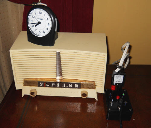
Here's my first version:
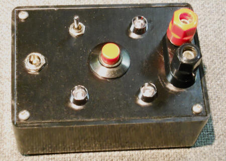
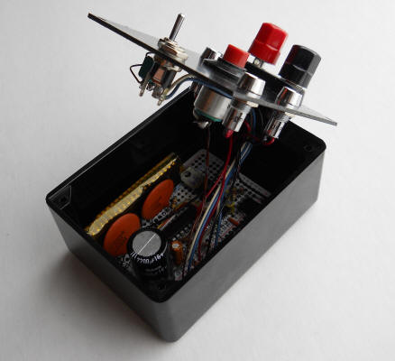
The big red button sets the time and the toggle switch stops the action. It has a spring return in one direction for momentary action to kill just today's action and a regular toggle action in the other direction to kill the action indefinitely. The lower-left LED indicates that the circuit is "programming," the lower-right LED blinks once per second, and the upper-right LED indicates when power is applied to the banana plugs. I added a 5 volt regulator and a PNP transistor that sources 5 volts to the banana connectors when the alarm is active, one hour per day:
5 volts was convenient since I'm using an AC output molded transformer "wall wart" for the supply - there's no place to "get" 120 VAC since it's hidden inside the power adapter. The 5 volts could power a relay for 120 volt devices or just gadgets that can be powered by 5 volts (like a 4.5 volt transistor radio). Here's a relay adapter I just built so this thing can turn on an old tube radio in the morning. I'll get a few seconds more sleep as the tubes heat up.

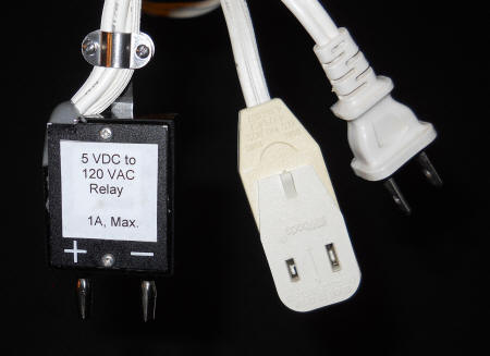
It works wonderfully! The old tube radio came on within seconds of the time when I pressed the button yesterday morning. It occurs to me to build this timer right into radios and other appliances to be controlled. A relay could be connected in parallel with the appliance's power switch so normal operation is, well, normal. Notice how the clock has nothing to do with the radio or timer. : )