This is a slightly modified version that addresses a few problems I've had with this circuit. This circuit is in Area 50 because it can be challenging for a beginner (and me, too).
This ionization chamber uses the drift/reset technique, but the reset occurs very early so that the reset pulses are fairly rapid, much like a Geiger counter. The top portion of the circuit uses two comparators in an LM339 to generate about 35 volts to bias the ionization chamber. The circuit is a modified Cockcroft-Walton voltage multiplier that uses a push-pull technique. Note: the "ground" symbol represents a common connection and the battery negative terminal, but the can is not connected to this common point. The can is biased up to about 35 volts above the battery's negative terminal. Make sure the circuit "ground" doesn't touch the can.
Pin 9 goes to pin 11 to save a couple of resistors. The voltage on pin 11 actually goes the "wrong" way for proper operation, but the divider makes it slower than pin 13, so it works fine. A purist might prefer to connect pin 9 to two 1 megohm resistors connected from plus to ground to generate V/2.
The bottom-left comparator monitors the source voltage of the electrometer JFET and switches to a low state when that voltage exceeds the voltage set by the potentiometer. That low voltage output causes the comparator on the bottom-right to switch to a high state, turning on the two BS170 transistors. The beeper beeps (clicks, really) and the chamber is discharged. (The discharge path is through the gate of the JFET and the BS170 to ground.) The RC delays in two places keep the comparator high long enough for a decent click sound to be produced and to completely discharge the chamber. The only capacitance is the wire itself and a 10pF directly from the gate to ground since I wanted it to charge quickly for rapid clicks. Make sure to set the 5k pot to a higher voltage than the source voltage with the gate temporarily grounded (clip lead is fine). It can be a confusing adjustment if the pot is set too low so try to come in from the top (higher voltage). Adjust for a click every several seconds.
Use a loud piezo buzzer to get a good click, something like the Intervox BRT1615P-06-C or even a few lower voltage types in series. It will let out quite a howl for a couple of seconds. A test source should give rapid clicks, much like a Geiger counter. But if it makes a buzz instead of a click the pot is probably set too low. After every adjustment wait a minute or two for things to settle. Even a plastic tuning tool can carry enough charge to cause the chamber voltage to wander off. It's most convenient to set the chamber on a radioactive lantern mantle or similar to supply a source of ionization.
Like most of these simple chambers, there are any number of ways to make it. I used a 2.5" tall, 7" diameter cookie tin and mounted a copper pickup ring on plastic necklace beads:
 |
 |
 |
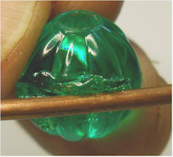
I melted a groove into the beads with my soldering iron tip and adjusted the length of the copper wire until it was snug. The diameter looks a little big, but it isn't critical. The important point is to insulate the wire very well. Most insulators aren't good enough. These styrene beads seem perfect for the job.
Note: Inside the smaller can, the gate of the jfet is bent up into the air and must not touch anything! It connects to the 100k resistor and 10pF cap to ground (not shown) but nothing else.
 |
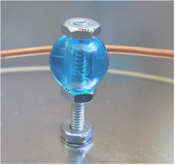
The gate lead is bent into the air and connects directly to the resistor and 10pF cap not shown (added recently). |
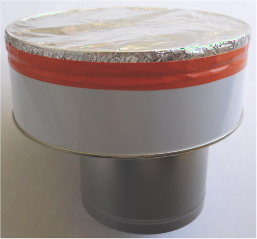
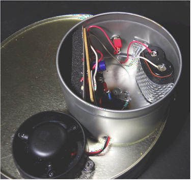
Fasten a suitable smaller can on the back of the cookie tin to house the electronics and add a feed-through made from another necklace bead for the chamber wire. (See the ion chamber page for details on how to use a bead as a feed-through.) Also add hardware to hold the buzzer and any bolts you might want to hold a handle. I didn't remember to and just used blind screws, hoping for the best! Fortunately, I didn't hit the loop. Cover the end of the chamber with aluminum foil, making sure the foil makes electrical contact with the lip of the can. A little sanding is a good idea.
 |
 |
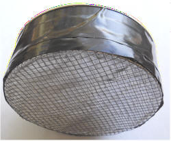 |
The foil needs protection so I just used a piece of poultry wire affixed with Gorilla tape (good stuff, by the way). I haven't figured out the pole yet. I'm thinking a broom or mop handle might be quick and easy. I made a short video of the unit in operation. That's two Fiestaware bowls, two lantern mantles and some pitchblende.
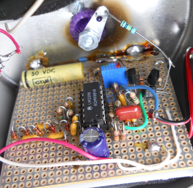
| I just crammed it all in there. I don't think I'd copy this internal mechanical design! |
 |
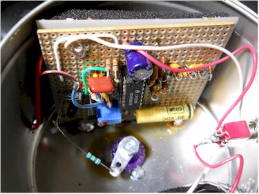 |
The solder lug on top of the purple plastic bead is the connection to the loop in the chamber. The plastic bead is melted into the can to secure it and a bolt runs through it to secure lugs on each side. The only purpose of that 100k resistor is to protect the JFET in the event I short the loop to the can.
The old LM339 is a pretty decent part. For one thing, it
will operate from only 2 volts or as much as 36 volts. The outputs are
open-collector, making it easy to "OR" them and to control higher voltages
than the supply to the IC. They have PNP input transistors so there's a
little current coming out of the inputs. That's actually handy when ground
sensing as it can be used to generate a slight positive offset. I used that
current in a V/F converter to ensure zero hertz out for zero volts in, for
example. They can also be converted to very slow op-amps, too (see the
application notes for details).
Those loud piezo buzzers are pretty handy "clickers." I used one on an old CDV700 in place of the headphones and it's loud enough to hear outdoors. No additional electronics, either!