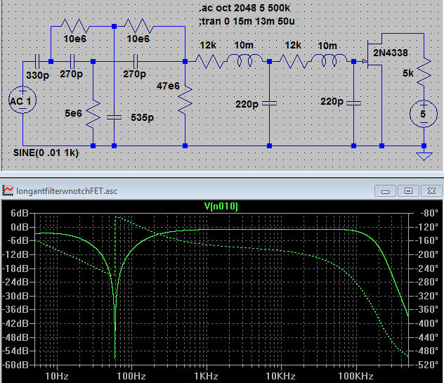
Here's a simple circuit for connecting to a vertical whip or long wire antenna for receiving audio frequency signals (see https://www.techlib.com/electronics/VLFwhistle.htm). The antenna plus cable should exhibit about 330 pF of capacitance to ground so add shunt capacitance as needed. This circuit is intended for setups where the antenna is connected via a fairly long piece of coaxial cable.
The notch frequency may be adjusted slightly by adjusting the 535 pF capacitor so that should consist of a fixed value, perhaps 470 pF and a variable trimmer, say 0 to 100 pF. Adjust the trimmer for the deepest null of the line frequency. The 5 megohm could also be adjusted in a similar manner with the theoretical value being near 9.8 megohm for 60 Hz.
The FET may be any of a number of types suitable for microphone amplifiers; I also like the J201. the 5k and 5 volt power source represent the circuitry on a typical soundcard. Just connect the drain of the FET to the tip and ring. The main problem with this approach is that there's no isolation between the receive ground and the usually-noisy computer ground. For those with unlimited funds, there are fiber optic USB extenders that will break the connection but a USB preamplifier would be needed at the antenna end. A more economical approach would be to replace the FET with a ground-sensing FET op-amp (the CA3140 is still sold) and use the output of the op-amp to drive an audio "interstage" transformer. The circuit would then run on batteries or a small power adapter.
OK, this has moved on from being virtual:
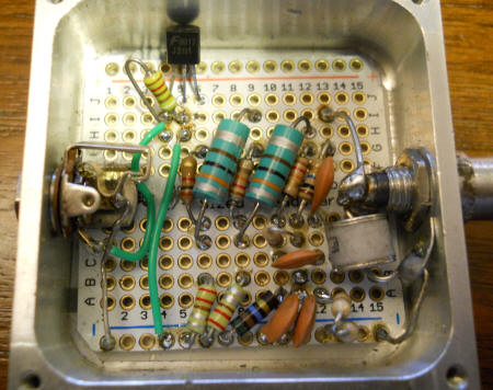
I made this for a friend and it's every bit as flat as the Spice plot. This needs to replace most of my other front-ends!
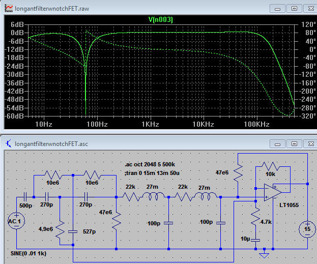
Here's an op-amp version. The op amp can be any number of FET input types, especially JFET types which have fairly rugged input stages. Note the unusual feedback to the bottom of the twin-T filter. That voltage bootstraps the bottom of the T, reducing the loading effect of the 4.9 megohm resistor. The 4.9 meghom resistor could be a 4.7 meghom in series with a 150k and a 100k pot and the 527 pF capacitor could be a 470 pF in parallel with a 47 pF and a 20 pF trimmer. Those variables would allow the notch to be fine-tuned, if desired. The 27 mH chokes are molded types - nothing special. This circuit is best for longer cable setups. Note the 500 pF at the input; that represents a fairly long coaxial cable to the antenna. Such a long cable significantly attenuates the signal but the RLC filter is much lower noise (about 25 nV/root-Hz) than the typical 1 megohm resistor (about 125 nV/root-Hz) often used at the front-end of such receivers. The result is that the atmospheric noise is well above the electronics noise for reasonably good op-amps by about the same amount as traditional receivers with direct connection to the antenna but with that 1 megohm in series. Note the nice, flat response out to 100 kHz followed by a steep drop thanks to the RLC filter. RC filters are adequate and eliminate the need for the inductors (see the next schematic).
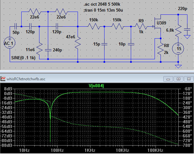
Here's a transistor version for direct connection to a short antenna as with a portable receiver. (Add about 39 pF to ground across a 1 meter antenna to get close to 50 pF.) Notice that the source of the JFET drives the bottom of the twin-T notch filter, increasing its Q and reducing the loading caused by the filter. This circuit also uses unusually high reactances in the notch filter to help reduce the loading. The 11 megohm and 240 pF may be a combination of parts as described above for fine-tuning the notch or the notch can be fine-tuned one time with fixed components. This circuit is quite low noise and will work well with just about any antenna setup. The roll-off of the AM band isn't as steep as with the RLC filters above but the attenuation should be sufficient. The 15 and 10 pF caps may be increased for a lower frequency corner. The output may be taken at the 6.8k and a buffer is recommended here. The voltage is about 9 volts on the drain and that can be used to drive a simple emitter-follower.
This file is a bipolar transistor low noise amplifier intended for low impedance sources. Note the very ordinary parts. Ordinary bipolar transistors like the 2N2222 or 2N4401 exhibit suprisingly low voltage noise, typically below 0.7 nV down to low audio frequency. There is significant noise current but for low impedance sources below about 1k ohm, that current noise doesn't contribute much to the total. The amp probably exhibits about 1 nV input-referred noise. The circuit has an input resistance of about 22k ohms and an input capacitance of around 100 pF, both determined by increasing the 100 ohm input resistor to find the 3 dB point. That 100 ohm resistor isn't part of the amplifier and represents the typical impedance of the signal source. The 1.1k resistor is selected to get exactly 40 dB gain. Removing the feedback resistor will result in about 65 dB gain with a roll-off just over 100 kHz. Current consumption is about 7 mA with a 9 volt supply and the output swing is about 4 volts, p-p.
Remember to always put a cap across the power supply - it isn't necessary in Spice but it is in the real world. For this circuit, I'd use a few hundred ufd.
The circuit is useful for amplifying the noise from a low-Z source like a power source or regulator (to measure the supply's noise output), diode mixer producing a baseband signal (after a low-pass filter that removes the sum frequency), dynamic microphone or speaker-as-microphone, low-resistance transducer, etc. Use metal-film resistors for best noise performance.
This file is an experimental audio amplifier that will drive a crystal earphone with lots of voltage while consuming only about 500 uA. Crystal earphones exhibit a high impedance to audio and a high voltage is needed to make them really loud.
The bias scheme is from a National Semiconductor application note from many years back. I think it was for the LM394. The bias is similar to connecting a resistor from the collector to base, but the second transistor acts like an emitter-follower for that collector voltage. The scheme thereby also biases the second stage with that emitter being about a half a volt above the first transistor's collector. In addition, that emitter voltage is bypassed by the 10 uF so there is little AC feedback which would reduce the gain and input impedance. The gain is set by a negative-feedback voltage divider (the 270 ohm and 68k) and by the step-up ratio of the transformer. The 270 ohm may be increased (up to about 10k) to lower the gain from 1000 to as little as 35. The resistor may be lowered for more gain, but the input impedance will begin to fall. Thanks to the feedback, the input impedance is high, about 500k. (Increase the 1000 ohm generator resistance to 500k and the gain will drop in half. That 1000 ohm is not needed in actual use.) The transformer is a 6:1 audio type with an 84 Hy primary and 2.33 Hy secondary. Note: the primary connects to the earphone. Other types will work, including lower turns ratios. Right-click on one of the inductors and you will see that I also included the measured DC resistance of the windings.
Stepping up the voltage with a transformer saves battery current and drives the earphone with more voltage. Notice that the swing is over 12 volts p-p below. With the values shown this is a very low noise amplifier, probably below 4 nV/root-Hz.
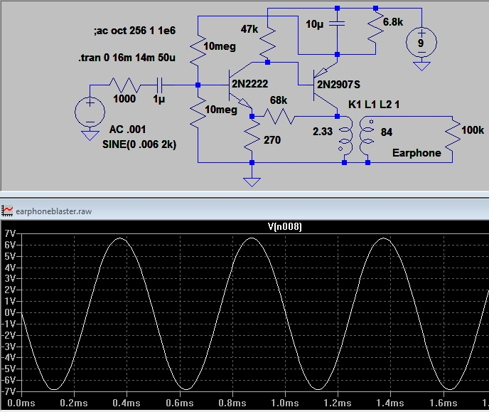
An input potentiometer could be added as a volume control, perhaps a 200k pot from signal to ground with the wiper going to the input capacitor. The transistors are not critical so feel free to try other small-signal types.
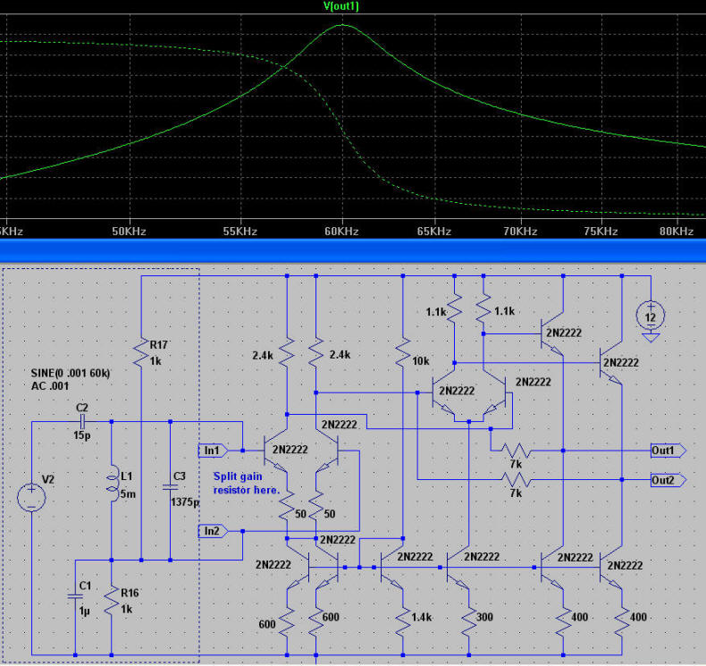
Update: Here's a better version where I changed some of the transistors to get a more realistic frequency response This one uses a single gain resistor and doesn't have the tuned circuit input.
I naively copied the schematic of a TL592 right out of the data book and selected some appropriate values. It seems to work pretty well when compared to working circuits! This particular file simulates 60 kHz coming from a short antenna into a simple tuned circuit. The parts in the box may be deleted and replaced with other external circuits. The gain resistor is split in two at the emitters, but that can be done in any number of ways - feel free to make changes. For example, you could remove the short between the two collectors and connect a single gain resistor between the emitters. I was interested in the possibility of injecting a current here to make an active mixer (a different project altogether).
Here's a homemade model for the LM6325 buffer with a few guesses for values. There's a source voltage and a capacitor-coupled 50 ohm load included. It seems quite similar to the actual part.
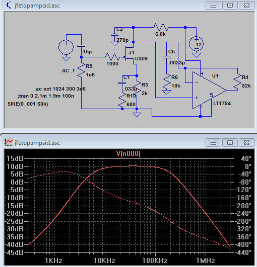
This file is a preliminary idea for a SID antenna unit that will cover the useful SID frequency band between a few kHz and about 100 kHz. The input impedance is high so a short antenna will be sufficient and the overall gain is inverting which helps with stability. If it turns out to need more gain, the 680 ohm resistor may be lowered and a little more gain can be had from this relatively slow op-amp. The JFET could be a J309 or possibly a lower current J201. I biased the JFET to have several volts from drain to source and to have about V/2 or a little more on the drain.
Replace the 15 pF with a .01 uF or something above 100 pF. The 15 pF simulates the antenna, a meter-long whip.
Here's an LM386 LTSpice model that seems to work exactly like the real thing. I've added a few odd current sources to more accurately simulate the real part. Transistors were chosen to give a quite similar frequency response. (If you don't have these transistors switch to 2N2222 and 2N2907. Drag the .asc file into LTSpice to change the transistors or make other mods then save. Restarting LTSpice is sometimes necessary to see changes.)
The zipped folder contains this schematic, a symbol and simple instructions for installing both. Your new part will appear in the AutoGenerated component folder. I've also included a typical audio amplifier circuit to try.