
It is often necessary to multiply the frequency of low noise oscillators without significantly degrading the phase noise beyond the theoretical 20 log (N). Low noise frequency doublers constructed with Schottky signal diodes are readily available but higher-order multipliers often exhibit high flicker noise and poor noise floors due to the nature of the switching device. An odd-order diode multiplier topology published in RF Design magazine allows the use of low noise Schottky diodes to generate odd-order harmonics with very low excess noise. A new, half-wave version of the frequency multiplier is presented along with component values for constructing a 10 to 30 MHz tripler and a 10 to 50 MHz quintupler. The conversion loss for these multipliers is good considering their passive design and the input return loss may be easily optimized for different input levels. The circuit for the multiplier is shown below:
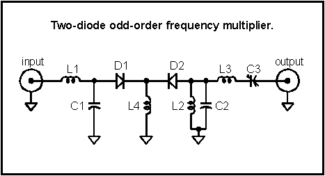
The input matching network consists of a choke and capacitor which work together to step up the voltage to overcome the diodes' barrier potential and to provide a low impedance to ground for the desired harmonic while preventing the harmonics form exiting the input. This series tank configuration gives the circuit a degree of feedback which helps to maintain a good conversion loss for a range of input levels. Diode, D1 rectifies the input signal resulting in a DC current in L4. The input signal commutates the two diodes with the result that a square wave of current flows in D2. The output network provides a low impedance to ground for the undesired frequencies and directs the desired harmonic to the output. Other networks may be used in the output circuit but the network should shunt undesired harmonics to preserve the fast diode switching and should block the larger, lower frequency harmonics. (Note: A current meter may be inserted in series with the ground leg of L4 to measure the DC diode current when prototyping.)
This basic configuration may be used for a wide range of frequencies with odd-order multiplication factors to 7 or more. Many fast-switching diode types may be used with excellent results and the choice will depend upon the signal levels and the required phase noise performance. Schottky-barrier diodes such as the 1N5711 are a good choice for most multiplier applications since the conversion efficiency is good and the phase noise performance is better than all but the best sources. Ordinary silicon switching diodes such as the 1N914 will give slightly better conversion efficiency for output frequencies up to 100 MHz but the phase noise performance may be significantly less than provided by Schottky diodes.
Figures 1 and 2 show the conversion loss for a 10 MHz input multiplied to 30 and 50 MHz. The conversion loss is quite low considering the multiplication factor and the 3x multiplier compares favorably with many frequency doublers.
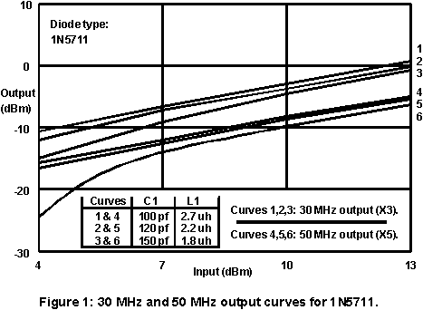
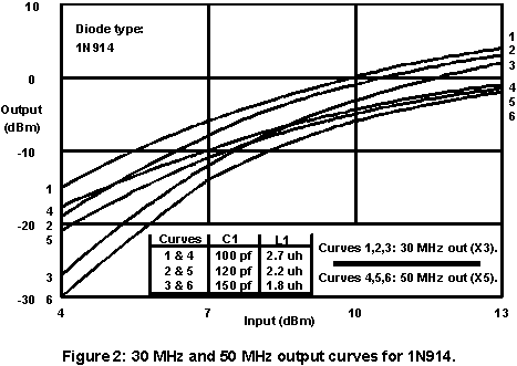
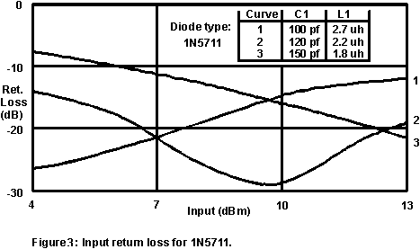
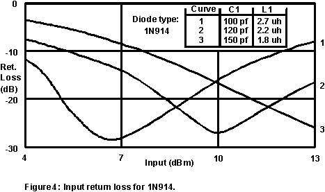
C1 and L1 are selected to give good return loss for the level applied to the input of the multiplier and depends somewhat upon the diode type. Figures 3 and 4 show the return loss for various values of C1 and L1 for the two diode types. For example, if the input level is to be 10dBm, curve #2 would be selected since the return loss is near -30dB. The other component values are selected from the following chart:
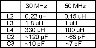
C3 may be a 15pF trimmer capacitor for both designs and C2 may be a fixed value with a small trimmer in parallel. The Q of the C2-L2 tank is low and fixed components will usually suffice.
The output of these multipliers may be directly connected to an ordinary MMIC amplifier. Choose a low noise figure amplifier if the phase noise performance is critical. The multiplier's intrinsic phase noise can be quite good if constructed with low flicker Schottky diodes. Flicker intercept levels as low as -148 dBc have been realized with the noise floor projected to be near -180 dBc. Few oscillators will be degraded beyond theoretical amounts by such performance.
![]()