
(Excessively Simple)
Imagine that one day you wake up to learn that all the GPS satellites have been destroyed. What's happening? War? Super-massive solar flare? Whatever it is you probably won't be spending the afternoon in your electronics hobby area. In all my years of playing with GPS it has never been "off the air." So, as a hobbyist, do you really need a GPS standard with "hold-over" that learns the properties of your oscillator and corrects the oscillator even when GPS is not present? (Hint: nope.) So why spend an inordinate amount of time and effort giving your standard a hold-over function you can only appreciate by physically disconnecting the GPS antenna? This unit provides an excellent 10 MHz reference as long as an accurate 1PPs is supplied by the GPS receiver. When GPS goes down you should be brushing up on your hunter-gatherer skills anyway.
This simple frequency standard uses the 1PPS available from many GPS receivers to lock a stable oven-controlled oscillator, holding a few hundred uHz of accuracy from moment to moment depending on the quality of the oscillator. (My old "Small Fry" wanders under +- 2 x 10-11.) It's a "nearly" analog circuit using three logic chips to perform simple tasks and a third-order phase-locked loop realized with two op-amps. The PLL behaves as though the lock frequency is 1 MHz due to the sampling technique (albeit updated only once per second) so the phase sensitivity is about 1 million times higher than if the phase comparison were done at 1 Hz.
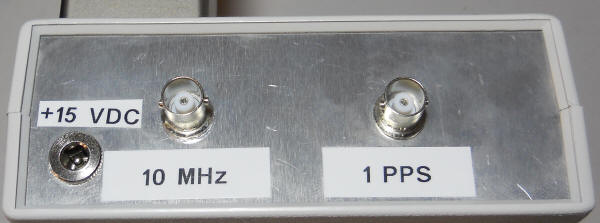
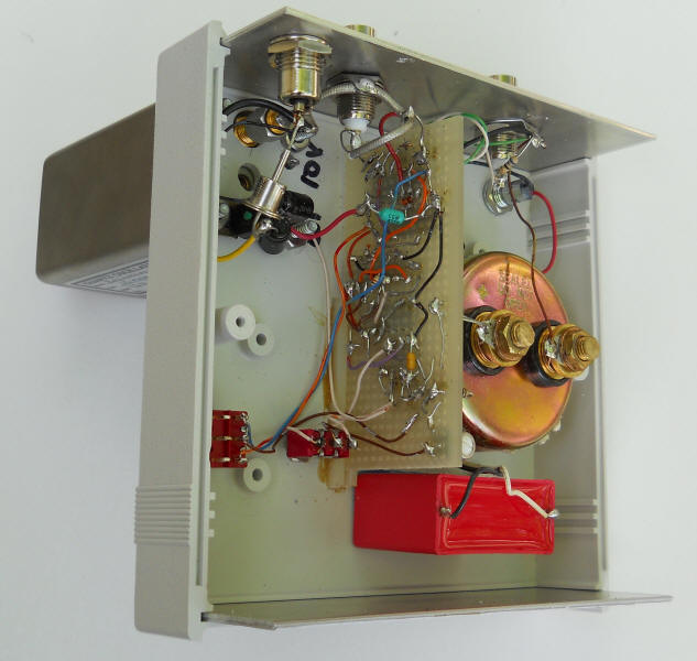
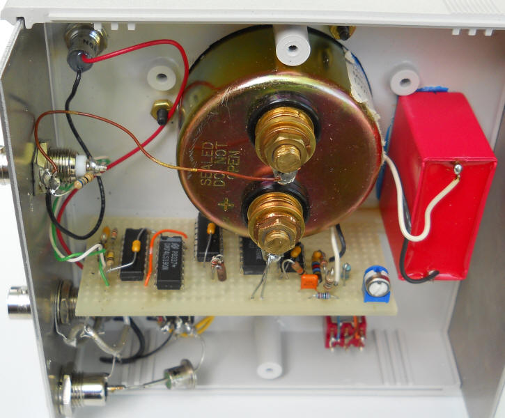
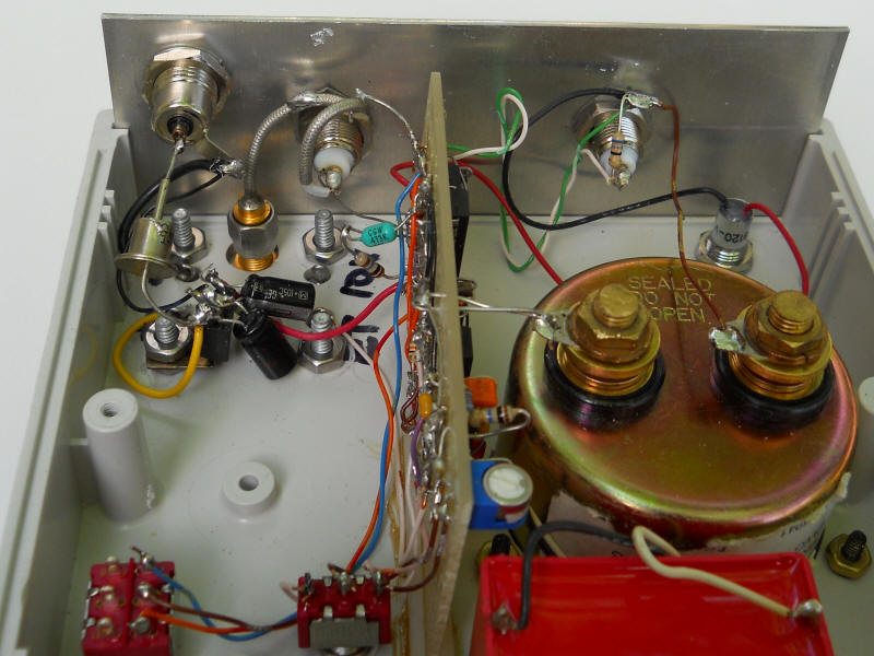
Starting at the left side of the schematic, the 10 MHz input is shown as an RF connector but the input impedance is sufficiently high that the circuit can be directly connected to the oscillator output on the back side of the output connector. No power splitter or buffer is needed. In my unit I connected the .01uF directly to the output connector with a short jumper wire. The gold SMA connector is the oscillator's output connector and the BNC is the unit's output connector. The short jumper wire is just above the green capacitor. (The green cap and resistor up in the air are the components on pin 11 of the 74HC14 that make the LED blink. The blinking LED was an afterthought but it's nice to confirm the 1 PPS signal is present.)

(Suitable ovenized oscillators are readily found on eBay for under $50. One could use a 5 MHz oscillator; just modify the divider to divide by five.)
The first stage uses one inverter in the 74HC14. Note that the feedback 100k (pin 1 to pin 2) is optional; it "undoes" some of the hysteresis to make the input a little more sensitive. It is not needed for oscillators with 7 dBm or more output. I just show it for those who have to deal with a wimpy oscillator. My "Small Fry" oscillator has a 13 dBm output and the resistor is unnecessary.
The output of the input square-up circuit drives a 74HC190 connected to divide by ten. Many divider ICs will work here, even an old SN7490. The output pulse width isn't critical as it is simply clocking the following flip-flop on its positive edge.
The next stage is a little more complex in function with the bottom flip-flop being the "tricky" part. The 1 PPS signal is buffered by two of the inverters in the 74HC14, the second being present to achieve a positive-going pulse. (Leave that second stage out if your GPS receiver provides a negative-going pulse.) When the bottom flip-flop (#2) is clocked high the voltage on the cathode of the diode jumps up via the 560 pF capacitor. The 1k resistor immediately starts to discharge that capacitor and when the voltage drops to about 2.5 volts the flip-flop resets, generating a 1 uS pulse that repeats at 1 PPS. The 1k and 560 pF determine the width of the pulse. Connecting the capacitor to Q instead of ground (as one might expect) causes the exponentially changing voltage to swing through a wide range making the circuit well behaved. This is a nice way to make very short pulses with stable width.
If you don't have a digital scope it can be difficult to check the pulse width. Temporarily replace the 1 PPS with a 10 kHz square wave from a generator. The 1 uS pulses will now be occurring fast enough to observe on an analog scope.
The 1 PPS pulse resets the top flip-flop (#1). Up to 1 uS later the 1 MHz driving the clock of the top flip-flop sets it high again. The bottom flip-flop also turns on the CD4016 (or 74HC4016, 74HC4066) analog switch for 1 uS and a sliver of voltage is applied to the RC low-pass filter on its pin 2. That 1 uS sample of the output of the top flip-flop will go high somewhere within that 1 uS window. If it goes high right in the middle of the sample window the voltage will average 2.5 volts. If the frequency of the oscillator is a little off, that DC voltage will vary from near zero to near 5 volts. Unlike ordinary mixers this phase detector outputs a sawtooth waveform instead of a triangle waveform. The nice result is that the slope of the sawtooth tells the user whether the oscillator is high or low in frequency simply by observing the slope of the voltage. Here's a timing diagram:

Restating: The 1 PPS positive edge triggers the 1 uS pulse at Q2. The first flip-flop is now active for 1 uS and is clocked high by the next positive edge of the 1 MHz signal. The analog switch is also closed for this 1 uS. At the end of the 1 uS pulse Q1 is reset and the analog switch is opened. The resulting pulses out of the analog switch are averaged by an RC filter to obtain the phase difference between the 1 PPS edge and the positive edge of the 1 MHz signal.
Since the 1 uS sampling window only occurs once per second the effective output impedance of the analog switch is very high; it's only connected for one-millionth of the time. To keep the DC value steady between samples the RC filter is buffered by an unusually high impedance op-amp, the LMC6582, Use a FET input type op-amp here.
The input (pin 1)of the 4016 connects to either pin 5 or pin 6 of the 74HC74, depending on the tuning slope of your oscillator. If your oscillator drops in frequency when the tuning voltage increases, connect to pin 6. A switch could be added here to accommodate different oscillators if the oscillator is not to be included in the case. If you get it wrong the circuit will avoid locking like the plague; just switch the wire.
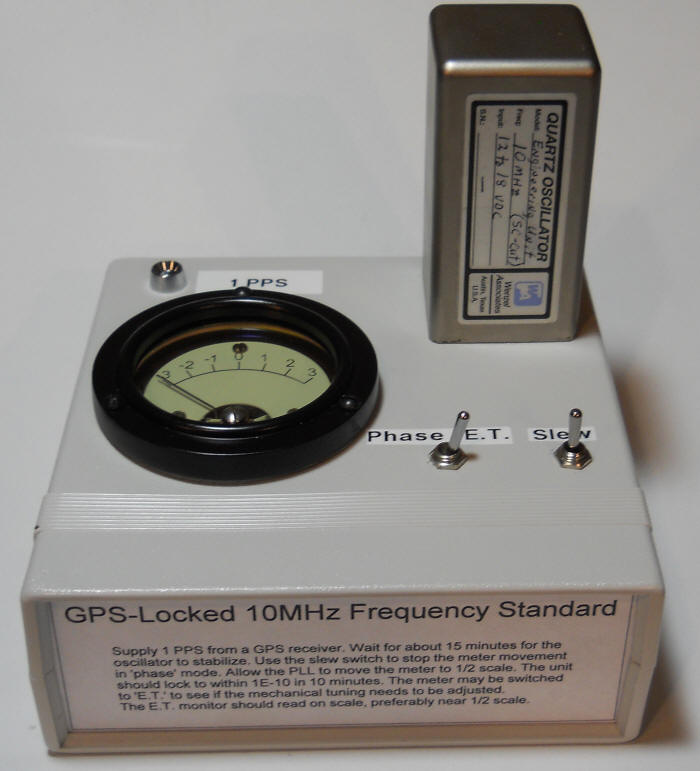
Initially I thought this would be the end of the project with the user fine-tuning the oscillator by hand to stop the phase drift. One could achieve a very tiny error in just a minute or two. But as I watched the nice "beat note" I realized that it would be a trivial matter to add a third-order PLL amplifier using the other op-amp in the dual package. It's a fairly straightforward circuit with a slew switch that allows the user to speed up the locking process; just flip the switch in the direction that slows down the beat note then let go when the meter is nearly stopped at center scale. Let the PLL take over and lock should be achieved in a few minutes. Don't bother trying to lock the unit until the oscillator has had plenty of time to warm up. The slew switch is fairly powerful so you may wish to slow it down by increasing the 470k resistor; otherwise you have to "flick" it to do the fine adjustment. Once your oscillator is tuned fairly closely you won't need to touch the slew switch; the single-slope phase detector ensures that the integrator is moving in the correct direction most of the time (once the oscillator is warmed up). My unit settles to within 1E-10 in less than 15 minutes and that includes the oscillator's warm-up time.
The PLL components are chosen to give good damping for a tuning sensitivity of 0.066 Hz per volt (measured at 1 MHz - that would be 0.66 Hz per volt at 10 MHz). A tuning sensitivity anywhere near this value will work fine, from as high as 1 x 10⁻⁷ per volt to a little as 3e-8 per volt. If you would like to see the settling response for a different tuning sensitivity here's an LTSpice simulation that will show the step response. You can simulate changes to the loop components to the left in the Spice schematic. A simple voltage divider will lower the tuning sensitivity of your oscillator, if needed.
Here are some photos of the inside of my unit but just about any assembly method is fine. The little potentiometer is in series with the current meter to convert it into a 5 VDC voltmeter. My meter happens to read +-3 full-scale so by adjusting the series resistor to let it "peg" slightly I can claim it reads "radians." : )
Also, when the unit settled completely I noticed the meter was a little off center - I just adjusted the zero screw on the meter but I could have tweaked that pot.
Your GPS device may not provide a 1 PPS signal that can drive 50 ohms. If that's the case you will have to experiment with resistors to get a good pulse. Try eliminating the 68 ohms to ground and add a 220 ohm in series with the 1 PPS signal at the GPS receiver end of the cable. That resistor is experimental and will hopefully dampen ringing so that the circuit functions properly. Alternately, build a buffer and locate it at the GPS receiver end of the cable. When it's functioning adequately the LED should blink once per second.
Note the old-fashioned "top hat" protection diode in series with the power. That's there to prevent damage if an incorrect polarity power source is connected. Directly beneath the diode is an ordinary 3-terminal 5 volt regulator and associated capacitors. You could simply run the circuit from a 5 volt molded supply. I wanted to supply the oscillator's power through the same power connector so 12 volts runs the oscillator and the internal regulator generates the 5 volts for the circuit. You might decide to not include the oscillator in the unit so that it can be used elsewhere. Just hook it up, let it settle and then measure the final tuning voltage. Use a potentiometer to apply that voltage to the oscillator tuning for when it's not connected to this device and you've calibrated it sufficiently for most purposes. I just happen to have oven oscillators coming out my ears so I dedicated one to the project.
If you end up with an oscillator that only has electrical tuning it's possible that your tuning sensitivity will be too high. Use a 5k potentiometer connected across a regulated voltage (usually supplied by the oscillator) to drive a series resistor connected to the electrical tuning, say 22k. Now connect another series resistor to the electrical tuning input for the PLL to drive, perhaps a 220k. The size of that resistors sets the electrical tuning sensitivity and the pot provides coarse tuning. Use the slew switch to center the meter in "E.T." mode then adjust the mechanical coarse tuning pot to stop the meter drift in "phase" mode. The same applies to adjusting a coarse tuning adjustor built into the oscillator.
Important: I built another on an Adafruit protoboard and struggled to figure out why it was less stable, taking unexpected jumps. It turned out to be nothing more than grounding. Here's a solution:
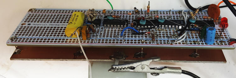
I cut a piece of copper-clad board about the same size and used it as a ground plane with several pins (from a Molex connector) connecting the ground strips on the protoboard. The problems vanished. The unit in the picture is actually under power and working great. I need to reconnect that LED that was causing "ground bounce" that should also be vanquished. The plated holes are of good quality and soldering/unsoldering from the top is fine.
One "design flaw" I found due to all this experimenting is excessive negative voltage on the flip-flop clear pin (13) when Q2 goes low. I've added a 1k in series with the pin to limit the current but the IC seems to discharge the 560 pF capacitor without ill effect as-is. HC data books claim the internal circuit can handle 250 mA pulses without misbehaving. AC logic (74AC74) has a tremendous immunity to such currents, rated as high as 450 mA and probably capable of more (according to an early Motorola "FACT Data" book. (Fact data is the best kind. : ) So, I suspect no resistor is needed since the flip-flop output will current-limit first.