Have you ever noticed how those technical-looking aneroid barometers in the stores all indicate a different pressure? And when you tap them gently they assume a new and equally meaningless reading. These are not precision instruments. And since they tend to stick, they aren't even useful for monitoring the rapid variations caused by passing storms. A home-made liquid barometer can exhibit excellent accuracy and repeatability and the response is nearly instantaneous. Since most liquids are much lighter than mercury, the sensitivity of the liquid barometer is much higher than mercury column types. Fig. 1 shows a schematic representation of the basic liquid barometer.

The liquid barometer uses back-pressure in the upper chamber instead of a vacuum to keep the column to a reasonable length (and to reduce vapor pressure problems). The top container must be airtight except for the tube extending down to the lower container. The bottom container is filled to a precise level with a liquid and is open to the atmosphere through a gap around the tube. A completely open container will also work at the bottom but evaporation may be a problem with some liquids, requiring frequent refilling. (One advantage of mercury barometers is the nearly zero evaporation rate.) The tube should extend well below the surface of the liquid. The tube must be quite long to accommodate the expected air pressure changes, the difficulty in adjusting the level, and significant changes due to room temperature variations if no temperature controller is used (see below). Water will move about a foot for every inch of mercury so a typical mercury scale of 29" to 32" would correspond to about 3 feet of water. The recommended mineral oil is even lighter and will give an even greater change. To accommodate a couple of feet of change and to make the setting easy, a five or six foot tube would be about right and the barometer will stretch from the floor to the ceiling. A shorter barometer is fine but a little patience may be necessary to get the level centered where it can move the necessary amount in both directions. Such a long barometer will change dramatically when storms blow by and is well worth the trouble to construct but the effects of room temperature changes will make the readings inaccurate.
A simple way to reduce the length of the barometer is to reduce the air capacity of the top container or increase the diameter of the tube. As the liquid rises in the tube, pressure will build up if the top chamber is small compared to the tube's volume and this pressure buildup will slow the column's rise. This short barometer will have a non-linear scale and is only recommended for observing significant pressure changes. This back-pressure technique is the secret to those attractive glass long-neck "swan" barometers which have a column height of only about a foot.
![]()
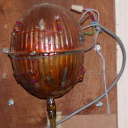
The professional mercury column barometer is relatively immune to temperature changes since the upper chamber contains a vacuum but the upper chamber of the liquid barometer contains air and the pressure of this air is proportional to the room temperature. If the temperature in the room varies by more than a few degrees, the accuracy of the simple barometer will suffer unless a correction scheme is used. One approach is to mark the scale with weather bureau comparisons made at one room temperature then develop a calibration curve for other room temperatures. The chart will show how many inches to add or subtract for different room temperatures. A superior approach is to control the temperature of the upper chamber using the scheme shown in fig. 2. The upper chamber is made from a copper commode float. Any similarly sized copper or aluminum container will work but choose a metal with good thermal conductivity for even heat distribution. The copper toilet tank float is well sealed, has great thermal conductivity, and is easily soldered. The stem of the float has a female thread and a small drill bit will fit inside and may be used to drill a hole into the float.
DRILL THE VENT HOLE BEFORE SOLDERING!
Eight, 270 ohm, 1 watt heater resistors are mounted to the float by soldering one lead to the copper and fastening the body of the resistor with epoxy. The other ends of the resistors are connected together and to the controller.
 |
 |
A thermistor is mounted in the same manner about 1/2 inch from one of the resistors. Make sure to strain relieve the wire connecting the controller to the free end of the thermistor. (A 10k negative temp-co thermistor is shown but other values may be used with a proportional change in the associated resistor.) The finished chamber is placed inside a suitable container and is insulated with fiberglass or Styrofoam. A wooden box lined with the foam insulation may be constructed for a nice looking upper chamber or a simple box may be fashioned from pieces of ceiling tile (a good thermal insulator). A small hole is drilled into the float through the threaded brass base (fig.3) and the tube is fastened onto the base forming an airtight seal. A copper or brass standoff or tube extension may be soldered to the float's base to allow the use of a clamp on the tubing. If the tubing fits snugly on the tube then the clamp may not be necessary but a little vinyl glue might be a good idea. The clear tubing protrudes through a hole in the bottom of the outer container down to the lower chamber. The clear vinyl tubing has a one-quarter inch outer diameter and a one-eighth inner diameter but larger tubing sizes will also work.
Fig. 3 shows the schematic for the temperature controller. This circuit is quite basic and most values and components are not critical. The components shown were selected primarily for
easy availability. The temperature setting resistor depends on the thermistor and should be selected to heat the float to a point that feels slightly warm to the touch (About 5.6k with a 10k thermistor). Temporarily connect a current meter in series with the power supply to monitor the oven's performance. The circuit should draw about 500 ma until the set point is reached and then the current should cut back to about 200 ma (depending on the set temperature). Reduce the set point resistor if the final current is much below 200 ma so that the chamber is hotter than the hottest temperature that the room might reach. Thermally insulate the float for this test. A little cycling before settling is fine but if the current cuts on and off repeatedly, then move the thermistor closer to the heater resistor or decrease the 330k resistor. If the final current is much above 200 ma then increase the 5.6k resistor to cool the float somewhat.
You may wish to add a permanent current meter so that you can monitor the oven's performance.
Higher resistance negative temp-co thermistors may be used by increasing the resistor connecting from the thermistor to the zener by a proportional amount. The thermistor and 270 ohm resistors are mounted on the float and the other components are mounted in a separate metal box. To simplify construction, connect the float to the negative terminal of the supply (negative ground) and connect the metal circuit box to the positive terminal (positive ground). This wiring allows the resistors and thermistors to be directly soldered to the float and it allows the 2N3055 to be directly connected to the metal case without insulating hardware. Obviously, the case must not touch the float.
The simplest way to charge the barometer column with liquid is to heat the upper chamber above its set-point by touching a soldering iron to the copper float or warming the float with a hair dryer. Air will begin to bubble out of the tube's bottom end which is submerged in the lower chamber liquid. After about a hundred bubbles come out remove the heat and allow the temperature controller to stabilize. The liquid will rise in the tube to an arbitrary height. If the height is too low then heat the upper chamber until additional bubbles come out of the bottom. The tube must remain submerged at all times unless the liquid rises too high in the tube and some air must be let back into the upper chamber. In this event, heat the chamber until all the liquid comes out of the tube and then remove the end from the liquid. Allow the upper chamber to cool a bit before submerging the tube again. A few attempts will give an acceptable level. Remember to consider the present air pressure when choosing the initial height. Set the level somewhat high if it is a high pressure day or low on a stormy day.
Keep the settings near the low end to minimize the pressure differential and thus the long-term drift. I have mine a little over two feet up for 30".
Check with the local weather station to get a current pressure number. Tape a piece of paper over the permanent scale and start marking pressure readings obtained from the local weather bureau. Eventually, a scale will become evident and may be permanently marked. Remember, some readings may not fit well due to some error either at the weather station or in the reporting so take several readings to average out the errors. Watch out for hours-old bureau readings if the pressure is changing. (Actually minutes-old readings can be misleading if you are trying for super precision.) The long barometer will have a quite linear response and the scale may be accurately extended and subdivided from a few good readings. Further fine tuning may be accomplished by changing the level in the bottom container or even by changing the temperature set point. Remember, this barometer is sensitive far beyond its accuracy, easily displaying changes and differences well below 0.01 inches of mercury so don't worry if your marks are off a few hundredths from the weather bureau. Don't let a perfect scale become an obsession because the absolute numbers are not as important as the smooth, quick response.
With the addition of a temperature controller, this home-made barometer offers near-bureau grade performance for fairly long periods. The only maintenance is an occasional addition of liquid to bring the level of the bottom container back to the calibration level (not likely necessary with mineral oil). (Refill at a particular air pressure since the level will change as liquid goes up and down in the column.) This level can be adjusted for minor calibration changes. If the barometer readings drop over time then the top container may have an air leak usually at the pipe connection or the float's coldweld seal. If the float's seal leaks then the seam may be soldered. Use plumber's flux to get a good solder bond but please clean the whole assembly with soap and water to completely remove the acid flux. Otherwise the residue will eat your components alive. Occasionally compare your readings with the official readings to verify the health of your instrument. The barometer will slowly drift as gas makes it through the liquid into the chamber and an occasional readjustment will be necessary.
 |
Note: The original Liquid Barometer used water but experience has shown that other liquids are better. Water evaporates easily, supports various slimy life forms, and transports gases from the ambient to the chamber too quickly. Ordinary mineral oil from the drugstore seems to work pretty well. It has few volatile components to spoil the vacuum and it is light which gives the barometer fantastic sensitivity. It is easy to see the column move up and down in a storm. Also, I have decided that the best approach is to wet the inside of the chamber with the liquid to help quickly stabilize the vapor pressure. Any extra liquid will seep down the tube and the column height will not be affected. If you get a bubble in the tube, simply "crush" it with some pliers. Smaller bubbles will result and these will float to the top. ( I am assuming a flexible plastic tube.) Use a container that can stand up to oil. The less-than-attractive prototype to the left uses a discarded transmission fluid bottle. |
Watch the barometer when thunderstorms are in the area-- especially if there is a tornado alert. The pressure will move surprisingly quickly as storm cells pass nearby. The basic barometer without the heater is fine for storm watching and an interesting "storm gauge" may be constructed by placing the upper chamber in the attic or outside with no temperature controller so that the outside temperature changes the column height along with the air pressure. Use a larger upper chamber container since the column length will be longer. Cold temperatures and high pressures will combine to give a high column reading which usually means clear, still weather. When the pressure drops on a hot day, the column will drop very low predicting severe weather. The tube for the storm gauge can pass through a small hole drilled in the ceiling in the corner of a room and should extend to the floor since the level will change dramatically. This "storm meter" hopelessly mixes two meteorological quantities, temperature and pressure, but then the "wind chill factor" does too. Calibrate the scale with temperature-pressure units by multiplying the weather bureau pressure and temperature readings. (First, convert the temperature to degrees above absolute zero by adding 273 to Centigrade readings or 460 to Fahrenheit readings.) You will find this unconventional instrument to be a good storm predictor.
� Copyright 1998, Charles Wenzel
Some additional comments:
I took apart an inexpensive aneroid barometer to see why it worked so poorly. There appear to be a couple of problems. First, the mechanism that converts the tiny movements of the vacuum chamber into a large meter movement involves an unlikely combination of levers, gears and bearings. It readily sticks and has an annoying "dead band" anywhere in which the needle is happy to sit. The other likely problem is the large spring that keeps the diaphragm from collapsing. It probably has a nasty temp-co and the tiny "adjustment" screw that pushes on the back is far too coarse of an adjustment. I don't think there is much hope for cheap barometers.
My local weather station makes small reading mistakes fairly often so accumulate several data points before drawing a scale. Remember, your resolution is better than most professional barometers - 0.01 inches of mercury is about 0.16 inches of mineral oil so you can easily resolve much finer amounts. In the grand scheme of things there is really no reason to know the absolute pressure with great accuracy. It is the trend that is most useful and even tiny changes might tell the amateur scientist something about changes in the air overhead. And with this barometer you can see a butterfly go by.
(No, not really.)
![]()
Sooner or later the weather hobbyist wants an electronic barometer, the main advantage being that it can be read automatically by a computer, chart recorder, or other data taking system. Most electronic barometers use some sort of strain gauge transducer to directly convert pressure to voltage and true weather bureau performance can be difficult to achieve with these pressure sensors due to their significant sensitivity to temperature changes. Compensated sensors are available but the compensation is only sufficient for coarse pressure measurements, sufficient for adjusting the fuel mixture in an engine but not good enough to read on the nightly news. However, by placing an uncompensated Motorola, MPX100 or similar pressure sensor in a precisely controlled thermal environment, a barometer with meteorological-grade performance results.
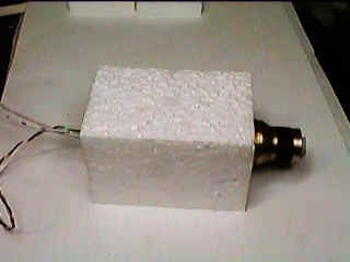
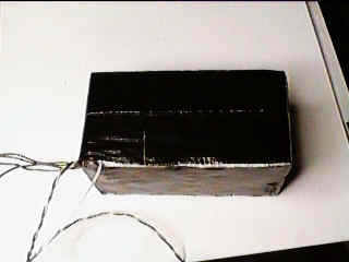
For this barometer ordinary copper plumbing fittings form the oven structure. A 3/4" end cap is soldered onto a 1 1/4" length of 3/4" pipe. A 3/4" to 1/2" reducer is soldered onto the other end to complete the enclosure. The finished assembly looks a bit like an artillery shell casing. An insulated thermistor is fastened to the inside of the oven with epoxy at about the mid point ( a bit like building a ship in a bottle) and the outer surface is wound with 35 ohms of resistance wire. In the prototype the enamel resistance wire is held in position by a single layer of Kapton tape. Lead wires are connected to the ends of the heater winding and strain relieved with black fiberglass tape. If resistance wire is unavailable, several resistors totaling 35 ohms may be glued to the oven for even heat distribution. ( I have several rolls of suitable wire so don't hesitate to request a few feet.) In the prototype the thermistor wires come out a tiny hole drilled in the end cap but they may also come out the open end of the oven with the sensor wires, if desired. The pressure sensor, voltage regulator and differential amplifier with lead wires attached are insulated with electrical tape and inserted into the oven. A couple of inches of the lead wire is pushed in after the sensor to reduce heat loss via the leads. A foam or plastic plug holds the wires securely as they exit the oven. The wires exiting the oven are folded back over the outside of the oven and taped in place to further reduce lead wire heat loss. The finished oven assembly is inserted into a 2" x 2" x 4" Styrofoam block drilled through to accommodate the oven. Two foam end caps are added and the foam is held in place by duct tape. With proper circuitry this simple oven will hold the contents to within a tiny fraction of a degree of the set point over wide ambient temperature changes.
The temperature controller circuit below uses an OP07 op amp but many ordinary op amps will work.
A few cautions are in order: the op amp output should be able to swing below 0.7 volts, the inputs common mode range should go as low as 2 volts or less and zero volts on one input should not cause a "phase reversal" where the output flips polarity from where one would expect (LM833 has this flaw, for example), and the op amp should be able to source 20mA or more. Most garden-variety op-amps meet these requirements, especially those billed as "single-supply" types. Make sure to choose an internally compensated op-amp or add the compensation components recommended by the manufacturer.
The thermistor is nominally 10,000 ohms at room temperature and changes about -3% per degree. Other NTC thermistors may work, especially higher resistance types but the temp. set resistor must be changed proportionally. When selected properly, the oven will draw about 150mA after warming up in the foam. Two, 22uF capacitors are connected back-to-back to form a non-polar 11uF capacitor but a 10uF polyester type could be used, if available. Just about any NPN power transistor will work but it will dissipate as much as one watt so it should have an adequate heat sink or be mounted with good air flow around it. The 12 volt supply will be required to source as much as 350mA during oven warm-up and about 100mA during normal operation. A small 5 volt regulator IC may be used in place of the 4.7 volt zener; just leave out the 3.3k resistor and connect the +5 volts where the cathode of the zener connected. Make sure to add capacitors to ground per the manufacturer's recommendations for the three terminal regulator. The op-amp must run on 12 volts, as shown.
![]()
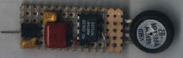
The pressure sensor I used in the prototype is a Motorola MPX100A that was bought along with a few others on eBay. These older sensors were probably not factory fresh; one exhibited noise (jumpy pressure readings) and one had an unusually high output offset voltage. The third one exhibits very little jitter and the output voltage seems about right. I don't know if such variability is typical or if these particular sensors have had a hard life. The sensors are quite easy to use; simply apply a regulated voltage across two pins and measure the differential voltage across the other two pins (an ordinary resistance bridge). The sensors are calibrated for zero volts out at zero pressure so at normal atmospheric pressure there is a small, positive voltage output. This positive voltage eliminates the need for a dual voltage power supply, artificial ground, or special biasing. An ordinary 4-resistor op-amp differential amplifier will boost the signal and convert it to a single-ended voltage but the prototype now uses an AMP04 differential amplifier thanks to yet another eBay find. The picture above shows the pressure sensor, amplifier, and 5 volt regulator ready to install in the oven. The amplifier is set to a gain of 10; additional gain and offset is accomplished outside of the oven. The large 0.47uF capacitor is installed per the manufacturer's instructions to achieve a low-pass function.
In the schematic above, the shaded parts are inside the oven. In my prototype the offset and gain are set such that the circuit outputs precisely 3 volts at 30" with a 1 volt per inch sensitivity. The two ovenized resistors (3.48k and 1.87k) were chosen to give a slightly low zero offset so that the 100k potentiometer would bring the zero to the desired spot when set near 50k. Since the 50k pot resistance is large compared to the divider resistors, the pot's temperature coefficient has little detrimental effect. The gain resistors (5.91k and 121k) were experimentally chosen to get the desired sensitivity. Such care in adjusting the offset and gain is not necessary since the offset and gain may be corrected in the qbasic software or even on the spreadsheet. But the offset must be set to move the output to the middle of the op-amp's range and the gain must be sufficiently high to get good resolution but not so high that the circuit runs out of voltage swing at the extremes of pressure.
The output of the circuit above could directly drive a meter or chart recorder or be read by a computer. A simple interface uses a serial com port and just a couple of bucks worth of ICs. The abbreviated parts list includes a CD4040 (12 bit counter - maybe $0.50), AD7541A (LTC7541AJN is about $4.50), LM7905L, dual CMOS opamp, and a few other odds and ends. The total cost should be well under $10 assuming you don't already have everything. A qbasic program converts the analog input and saves the data to a file. A openoffice.org spreadsheet automatically reads this file every few seconds and plots the data. Here is an actual pressure chart made with this barometer and software:
(The spreadsheet was modified to convert the voltage readings into pressure by adding another column.)
By the way, if you are using Windows 95 or later, you will probably need to browse the Windows CD to find qbasic.exe. Look for a folder with a name like "oldmsdos". (Or, GWbasic is readily available and probably compatible with my program.) The openoffice.org spreadsheet also has a basic-like macro capability but I couldn't figure out how to directly talk to the serial port registers.
![]()
We just had a couple of cold fronts roll in, bringing rain. Watching the electronic barometer plot on an expanded scale I saw the pressure climb as expected but about the time the rain started, the pressure plot became "noisy", jumping around a few thousandths of an inch minute to minute - too small to see on my precision mechanical barometer but easily seen on the spreadsheet. After the rain stopped, the noise stopped too. Am I seeing minute-to-minute pressure changes due to falling rain, rain cloud movements, etc? I wonder what info could be hiding in those tiny variations? The plot below is another front with rain arriving. Notice the "noise"; it was already raining when I started this plot. The rain stopped near the middle of the plot and so did the noise.