This project is a bit dated. I'd probably buy a Lithium battery charging/maintaining circuit board. I've seen nice ones for under $10. Add a modern Lithium Ion/Polymer battery and a suitable solar panel and you're done; the little PCB takes care of the somewhat fussy lithium battery pack. Granted, it's not really homemade at that point and you could just buy the whole thing. That's progress for you.
The battery charging portion of the project is shown below. This circuit will keep a 6 volt NiCAD battery (b1) topped off with a few hours of sun every day. Add a low-dropout, micro-power regulator to generate 5 volts to drive most USB-powered phones and other devices (further down the page).
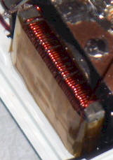
It is mandatory that a fuse be added near one of the terminals of the battery! (See the little green 5 amp fuse along the bottom edge of the battery.) Battery packs can supply dangerous current levels! Keep the lead from the fuse to the battery terminal as short as practical for safety.
This little gadget uses a small 3 volt solar cell to charge a 6 volt NiCad battery pack which, in turn, may be used to charge many models of cell phones and other portable devices with the addition of a suitable low-dropout voltage regulator. The circuit "scavenges" energy from the solar cell by keeping it loaded near 1.5 volts (maximum energy transfer value) and trickle charges the internal battery pack with current pulses. The simple circuit isn't the most efficient possible but it manages a respectable 70% at 100 mA from the cell and 30% when the cell is providing only 25 mA which is actually pretty good without going to a lot more trouble or using more exotic components.
Note: This circuit is intended for using a low voltage cell to charge a higher voltage battery. Don't use it to charge a battery at the same or lower voltage than the cells generate. The circuit needs a battery load to work properly. Make sure to use a NiCAD battery as they are tolerant of overcharging. Leave the unit in a sunny place and the battery should stay good for years.
Battery Charger Parts:
| Ref. | Description |
|
| PC1 | 3 volt solar cell from a sidewalk solar light | |
| C1 | 22 uF, 10 volt (values not critical) | |
| C2 | 100 pF, any voltage or type, typically ceramic | |
| C3 | 10 uF, 16 volt or more for higher voltage battery | |
| R1 | 1.5 k, any type | |
| R2 | 3.9k, any type | |
| R3 | 10k, any type | |
| R4 | 180 ohm, any type | |
| R5 | 4.7k, any type | |
| R6 | 10 ohm PTC (see text). | |
| L1 | 50 to 300 uH (see text) | |
| D1 | 1N5818 schottky rectifier, just about any will do. | |
| Q1 | 2N4403, or similar | |
| Q2 | 2N4401, or similar | |
| J1 | output jack | |
| B1 | 6 volt NiCad battery w/fuse |
Here is how it works:
When the voltage on the emitter of Q1 rises a little over 1.5 volts, both transistors turn on quickly, snapping on due to the positive feedback through R5 and C2. The current increases in L1 through Q2 until the voltage across the cell drops somewhat below 1.5 volts. The circuit then switches off quickly and the voltage on the collector of Q2 jumps up, turning on D1, allowing the inductor current to flow into the battery. Once the inductor has discharged into the battery, the process starts over. The circuit can charge higher voltage batteries without any circuit changes since the voltage will jump up quite high on the collector when the transistors turn off. The circuit should not be operated without a battery attached. For a little more efficiency, increase R5 in proportion to the voltage increase on the battery. (For example, double R5 for charging a 12 volt battery.) A NiCad battery was chosen because they are particularly forgiving of overcharging, simply converting the excess current into heat.
The photocell was salvaged from an inexpensive solar sidewalk illuminator and it has an open-circuit voltage of about 3 volts and supplies about 100 mA in bright sunlight. The circuit can handle more current but avoid cells that supply more than 250 mA. The inductor should have a low resistance winding but a surprising number of cores will work fairly well. The core in the prototype is actually a piece of ferrite antenna rod chosen simply to fit in the extremely limited confines of the package. Another unlikely inductor that worked well was 10 turns on one of those 1" long, 1/2" diameter large ferrite beads often used for power line baluns! The value of inductance isn't critical, perhaps between 40 and 300 uH and during proper operation there will be a pulse waveform on the collector of Q2 with several 10s of microseconds period. This prototype operates at about 40 uS as shown and the inductance measures about 50 uH.
For experimenting with cores or other circuit values and to make sure it's all working properly, replace the NiCad battery with a zener of the same voltage and replace the solar cell with a 3 volt power supply with a series resistor, about 22 ohms to simulate moderate sun. Measure the current in the zener and compare that power (zener current times zener voltage) to the power coming from the power supply (3 volts times power supply current) to see how the circuit is doing. When the power in the zener is over half the power from the supply, the inductor is good enough.
Ugly Construction - But it Works!
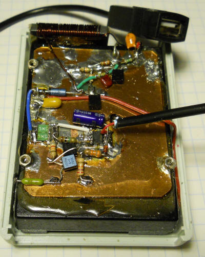
My little green fuse ended up in the negative battery leg and goes directly to
"ground" (bottom-left in photo). It's a 2 amp fuse but a little higher is
recommended. It's just there to prevent "disasters."
Don't copy my assembly technique! First of all, I had to cut all the mounting posts out of the case to get the battery to fit and it is held in by glue. Notice the silver nuts soldered onto the PCB for securing the cover! Secondly, there is very little height for the circuitry so everything is pressed down flat against a piece of copper clad board using little bits of board for the connections. That's a fine technique but this prototype was just too tight for comfort. Third, I had to search a while to find an inductor that would fit!
You need to add a 5 volt regulator to power a USB device and this regulator needs to be a low-dropout type that consumes "micro" power so that it doesn't discharge the battery on its own. There are commercial regulators like the TPS76750Q in the PWP package that will do the job with just a couple of good ceramic bypass capacitors. (There are a bewildering number of suitable regulator choices.) But if you like to build your gadget from parts on hand, below are a couple of circuits that will work. The first is the one I ended up using:
The two PolyFuses limit the current from the battery to about 1 amp but Smartphones and other USB-powered devices should draw less than 500 mA using a standard USB socket with the data pins not shorted (recommended). The P-channel mosfet may be any type with a couple of volts or less turn-on threshold (Vth) and capable of handling a few amperes. However, many types require too much voltage to turn on for this circuit.
Power dissipations should not be an issue in most cases but it wouldn't hurt to check the dissipation rating on your pass transistor. The older part I used can dissipate a watt with no heat sink and the actual dissipation should stay under 800 mW with a fresh battery and a full load of 500 mA. I soldered the leads of the surface-mount package to fairly large pads so it should handle well over one watt.
Vary either the 33k or 27k if the voltage isn't near 5 volts. The circuit should hold the voltage within about 50 mV of 5 volts for no load to full load over normal temperature variations. The circuit draws about 175 uA and that's less than the self-discharge of the NiCAD battery pack so no power switch is needed. You can also reverse the polarity of everything and use an N-channel mosfet. Remember, many mosfets require too much gate voltage to turn on - look for one with a Vth below 2 volts. the NDS8434 threshold is typically 1.5 volts. My N-channel version couldn't supply the full 500 mA because the circuit couldn't quite pull the gate voltage high enough.
If you don't have a suitable P-channel mosfet and don't want to worry about the mosfet characteristics, build the circuit below. The MPSA63 can be just about any small-signal PNP darlington and the 2SA2023 may be any number of small power PNP transistors. This circuit is less fussy regarding the transistor types as there is plenty of gain and the "turn-on threshold" of the PNPs is sufficiently low and stays the same regardless of transistor types.
How it works: The LM385 applies 2.5 volts to the base of the 2N4401 and the diode and two feedback resistors apply a divided-down version of the output voltage to the emitter. When the output voltage is low, the emitter voltage is below the base voltage and the transistor conducts. The voltage on the collector drops, turning on the mosfet or the PNP transistors. The MPSA63 is just an emitter-follower that boosts the current to the base of the 2SA2023. When the voltage on the output rises to a sufficient level, the 2N4401 begins to turn off and the current in the pass transistor drops to whatever value is needed to maintain 5 volts out. The diode in the feedback compensates for the 2N4401's base-emitter diode drop for good temperature stability. I believe the specification for USB power allows for +- 250 mV variation and this circuit will regulate about a factor of ten better than that over a fairly wide temperature range. The drop-out voltage on this circuit is so low that it will still provide a valid output voltage when the NiCAD has discharged to 4.9 volts!
USB Pinout: Search the web for a pinout image. The power is on the outer pins but if you cut a USB extension cable in half the way I did (using the female end for the project), you might discover that the wires are properly color-coded with red (or orange) being plus and black (or blue) being minus. Looking into the end of the connector with the conductors facing down, the pin on the right is +5 and the pin on the left is ground. Boy, it's easy to get confused! You can plug the candidate connector or cable into a computer using another USB cable and verify the voltage with a meter - highly recommended!
You don't "need" the polyfuses, but they're recommended and you really must have a 5 ampere fuse in series with the battery. If you use a commercial low-dropout micro-power regulator IC, you can skip the polyfuses since the IC will have current limit and thermal shutdown. But keep the fuse! I'd connect the battery as the last step to avoid unnecessary fuse-blowing.
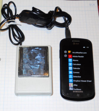
It works great! I simply leave it on my dash until I need it. It is actually more convenient than a cigarette lighter adapter because it can travel with the phone and it doesn't need sunlight to charge the phone.
![]()
Here is the schematic for the automatic charger I have been using for my
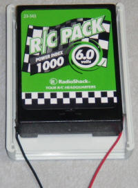
kids' battery cars. The charger is a small molded unit that probably doesn't supply
more than an amp and this circuit would have trouble with much more. No current limit is
provided by this circuit - it relies on the charger for that. The circuit could be
modified to provide more current by lowering the 470 and 330 ohm resistors in the 5195's
base circuit and the 10k in the collector of the 4401. A relay could also be used in place
of the pass transistor.
Here is how it works: When the battery voltage is low, the voltage at the base of the
first 2N4401 (on the right) is not sufficient to turn it on and the second 2N4401 is biased
on by the 10k resistor. The power transistor is turned on and the LED lights. When the
battery is fully charged the voltage will exceed a somewhat arbitrary
"over-voltage" value slightly below 14 volts and the regulator will switch off.
The 470k feedback resistor gives the circuit some hysteresis so that it will not turn back
on until the battery voltage drops below about 13.5 volts. When the battery is nearing
full charge the light will begin to flash on and off and after a few hours the light will
only come on occasionally. This occasional over-voltage jolt sure seems to keep the
batteries in great shape.
![]()
Here is an experimental (and simple!) regulator for alternator chargers. Q1 and Q2 are medium-power transistors and Q3 is a high-power type. The zener, D1 is chosen to set the charged voltage and will be about 10 volts for a 12 volt battery. The 0.1 ohm resistor sets the maximum field current. Not shown is the connection from the output of the alternator to the battery. An AC alternator will need a diode rectifier but most car types have the rectifier built in.
When the battery is low, current flows through the 0.1 ohm resistor and Q3 to the field coil. The voltage across the 0.1 turns on Q1 which limits the current in Q3 (about 0.7 / R or 7 amps in this case). When the battery is charged to about 14 volts, Q2 turns on and turns off Q3, stopping the charging.
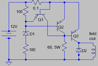
This circuit is just a concept and has not been built and tested.
![]()