
When your cellular phone receives a call, it begins transmitting even before you answer. The circuit shown in fig.1 detects this signal and can operate a variety of devices referred to as "load". The LM10 is hard to find so use a micropower op-amp that can run on 9 volts and that can sense ground on its inputs. Connect the 470k from the negative input to the battery plus. Increase that value to 2.2 megohm and lower the value of the 39k to 3.9k or select for the desired sensitivity.
For times when a loud beeping is unacceptable, the load could be a small motor with an offset weight on the shaft so that it vibrates when the phone receives a call. (Add a switch in series with the battery for this application to stop the vibration while you talk.) Or the load could be a lamp or lamp/flasher circuit for a visual indication of an incoming call. The load could be a timer, tape recorder, or even an interrupt line on your laptop to bring up a call logging program. (That one might be rather challenging.) At the other extreme, the detector could be used to generate a louder ringing signal or even honk the horn for when you leave the phone in the car. The circuit will work well from the car’s 12 volt battery and the current consumption is so low that a power switch is not included. The only critical wiring involves the diodes, antenna, and .01uf capacitor. Keep these leads short and the circuit should work fine. If the sensitivity is too high then increase the value of the 39k resistor. Other RF Schottky diodes or fast silicon diodes may be substituted and even 1N914s may work adequately well. Use insulated wire for the antenna and keep it fairly straight although bending the antenna to fit inside a small plastic enclosure won’t hurt the performance much. Substitute a cmos op-amp for the LM10 with different voltage divider values for the trigger reference to reduce the standby current to virtually nothing for applications powered by tiny batteries.
Copyright, 1995 by Charles Wenzel
![]()
The circuit below is a more sensitive version for newer digital phones designed to mute the car stereo or drive other loads. The detector is a biased Schottky diode and the detection threshold voltage is adjustable and temperature compensated with another 1N5711. The first op-amp in the LM358 acts as a comparator and the second op-amp remembers the trigger for several seconds so that the circuit does not drop out with temporary signal fades. An optional LED is included to monitor the comparator output. Adjust the 2 megohm potentiometer until the LED just goes out for maximum range. The antenna in the prototype is a stiff wire a few inches long and trimmed for maximum range. The whole circuit could be built into a small box that mounts on the visor or behind the headrest to minimize the distance to the phone.
The more enterprising experimenter who wants more range may wish to add a MMIC amplifier in front of the detector since plenty of power is available in an automobile. (See mfg's. application notes for simple circuits. www.minicircuits.com , for example)
Here is a photo of the prototype:
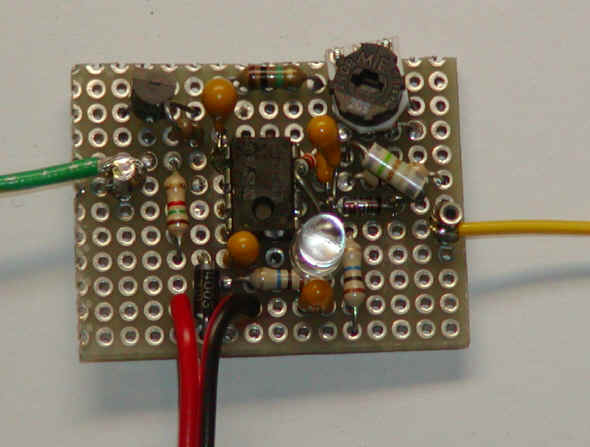
The 1N4003 between the power leads is an optional "idiot diode" connected in series with the power to prevent damage in the event the power connections are reversed. The wiring is not critical except for the first diode and the .1uH choke (.15 uH in the prototype) which should have short leads. The 2N4401 can handle several hundred mA loads but a power darlington or mosfet transistor could be substituted (see first schematic above).
![]()