
An RF isolator is a seemingly magic device that allows signals to pass in only one direction. Signals applied to the input port are sent to the test port and signals coming into the test port can only go to the output port. This one-way property is usually accomplished with special non-linear ferrite/magnet structures operating at very high frequencies. Fig. 1 shows an active RF isolator capable of handling signals approaching 16 dBm and frequencies from well below 1 MHz to above 200 MHz. The circuit really emulates an isolator in that the actual signal energy is not passed from port to port and the signal levels must be fairly low. The circuit is well suited for testing the SWR of a variety of devices connected to the test port. Make sure to read about Joe's improvements below.
For a typical setup the test generator is connected to the input port, the antenna or device to be tested is connected to the test port, and a signal level monitor is connected to the output port. When the test port is terminated with 50 ohms, no energy is reflected and no signal will appear at the output port. If the load at the test port is not 50 ohms then some of the test signal will reflect and appear at the output port. For example, if the test port is completely open, the test signal reflects completely and the output will equal the input. If the test port is shorted, the test signal will reflect inverted and the output will be an inverted version of the input. Other loads will reflect a portion of the test signal - see SWR.
To measure the return loss of a device or antenna, first open or short the test port
and observe the signal level at the output port. Then connect the device to be tested and
observe the drop in signal level at the test port. The amount of drop is the return loss.
This test may be done in the presence of other signals if a tuned meter or spectrum
analyzer is used to monitor the test signal. Adjust the test signal frequency until it is
sufficiently far from the other signals to easily measure and verify that the other
signals present are not too large for the circuit to handle (below 16 dBm).
The chokes in the emitters should have a reasonable impedance at the frequency
of interest and a series combination of small and large value choke will give
the best bandwidth. Multi-hole ferrite beads are a good addition for the higher
frequency end. Also, some blocking chokes are wound to look inductive over a
wide range of frequency with one end typically being the best for the RF side.
Look for a paint dot or windings that taper down to a single layer with space
between the turns to identify the RF end.
The transistors will run hot so use a low-capacitance heat sink. Increase the 10 ohm resistors in the emitter circuits to reduce the transistor heating but the large signal handling ability will be reduced. The isolator is a 50 ohm device due to the resistors near 50 ohms. (The 56 ohms are a bit higher since they are shunted by some circuit resistance.) Other impedance like 75 ohms may be achieved by changing these resistors to, say, 75 and 82 ohms. Ordinary small-signal transistors like the 2N3904 operating at much lower current make a useful device for testing antennas and low power devices at lower frequencies - perhaps to 50 MHz. Try 2, 82 ohms instead of the 2, 10 ohms in the emitters. Remember that the signal handling capability will be quite low so use signals at or below 0 dBm (1 mW).
Some points for the experimenter to ponder:
Also read about an IC version of the isolator: Low Frequency Circulator/Isolator Uses no Ferrite or Magnets (pdf file)
Reader Joe (WA9CGZ) built a snazzy version of this isolator and offers these comments:
I used 220 uH with two ferrite beads for the inductors in the emitters. I had to add a bead on the base of the '5109 facing the test connector to stop VHF oscillation. As built from the drawing, I could only see about 20 dB return loss using a 50 ohm load on the test port. I found that by adding a small trimmer capacitor between the emitters of the first pair of transistors and changing the 56 ohm resistor on the collector of the transistor to 66 ohms, I could improve the return loss to better than 30 dB.
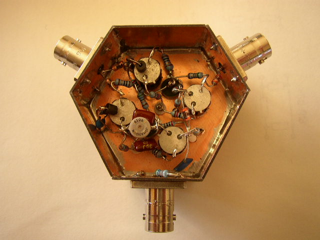
Thanks Joe!