
![]()
Some comments about this project:
|
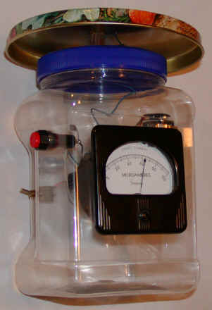
Here is a simple electrostatic charge monitor that may be used to detect any slowly changing electric field including charges swirling around in a thunderstorm or the charge on a moving pocket comb from across a room. The heart of the circuit is an electrometer-grade JFET marked "SPF3059" which is like those found in many smoke detectors, similar to the PN4117 or 2N4117.
 |
 |
This charge monitor prototype is intended to be a "hand held" instrument and it is not weatherproof at all. This is really just a fun toy and too much effort in packaging might be inappropriate! Most of the circuit is mounted on the back of the meter with a couple of terminal strips and a single teflon terminal for the antenna connection. The antenna is the lid from a small cookie tin and it is raised above the plastic lid by a single phenolic standoff but it could be flush mounted, if desired. I wanted it out of the way a bit.
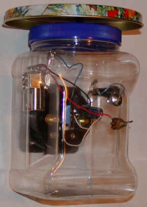
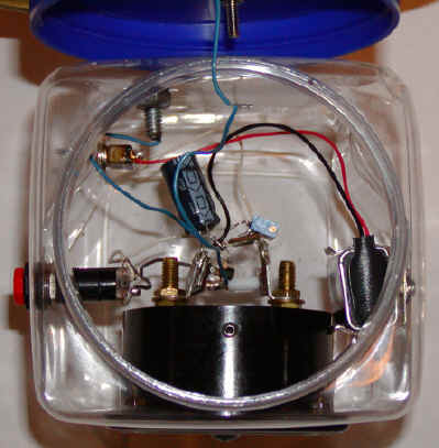
The antenna connection is very critical and if you don't have a teflon terminal, just float the wires in the air, making sure they don't touch anything except the zero switch. You might suspect that the zero switch and 150pF capacitor would be a problem but normally there is little voltage across these parts and, consequently, leakage is not as serious. In fact, a little leakage here tends to help "auto-zero" the circuit. Use a low leakage polystyrene, plastic or glass capacitor of 100 to 1000pF. A ceramic capacitor may have too much leakage. Use a good, clean switch, too. (If too much leakage occurs here, the capacitor will discharge too quickly and the meter will drift back to center a little too quickly.) A bolt was added as a finger pad to bring the circuit ground to the same potential as the person's body holding the meter. Touch this bolt while holding the jar to stabilize the readings a bit.
Here is how to set it up:
Clean everything with a good degreaser (circuit wash, alcohol, acetone, etc) and dry thoroughly with a hair dryer. Take care not to damage the plastics if you are using something aggressive like lacquer thinner! Temporarily disconnect the 2,200 uF capacitor, turn on the power and wait several minutes. Press the zero button and, while holding it, adjust the pot until the meter reads half scale. This adjustment should be permanent unless you have leakage problems or the 2,200 uF capacitor is unusually leaky. Reconnect the 2,200 uF capacitor and wait several minutes again. Press the zero button several times until the meter settles near half scale. Now lift your foot off the ground and you should see a change. Try running a comb through your hair then waving it near the antenna. A properly operating meter should respond to the comb from yards away. Push the zero button occasionally to center the meter. Sometimes a static charge can build up on the plastic. Simply run your fingers over the surface of the plastic while touching the ground screw with the other hand to discharge the plastic.
Here is how it works:
When the zero pushbutton is held in, the gate of the FET is connected directly to the variable voltage provided by the potentiometer. This voltage sets the source voltage to a value that gives 50uA drain current giving a half-scale meter reading. When the zero switch is released, the 150 pF capacitor holds the DC voltage constant as long as there is no significant leakage current. The capacitor forms a divider with the antenna capacitance and any electric field the antenna experiences induces a voltage at the gate, changing the meter reading. The 2,200uF capacitor grounds the source of the FET for AC signals giving the circuit much more gain for changing signals. The time constant is long so the meter has good sensitivity for even slowly changing fields. The leakage is so low that the voltage will stay constant on the 150pF capacitor for long periods! The prototype works well with no capacitor except the capacitance of the antenna!
![]()