T1: Unless you plan to test high-power devices, T1 may be a small power transformer with a few different secondary voltages. The prototype depicted in the schematic has four secondary taps but a center-tapped 24VAC transformer will give two useful test voltages of about 17 and 33 volts peak. Avoid voltages much above 24VAC to reduce risk of shock.
S1: A single-pole switch with enough positions to accommodate the desired number of test voltages.
S2: A two-pole switch with enough positions to accommodate the desired number of test current ranges. Note that the switch selects resistor pairs: R1 & R7, R2 & R8, R3 & R9, R4 & R10.
R1 - R4: These resistors limit the test current. R1 could be a 100 ohm, 10 watt resistor for a high power range capable of testing incandescent lamps (and quickly zapping semiconductors!). R1 works with the current sensing resistor R7. The current sensing resistors should be about 1000 times smaller than the series resistors so R7 should be 0.1 ohms if R1 is 100 ohms. The power dissipated in the current sensing resistors will be small so any style may be used.
Try R2 = 1000 ohms, R3 = 10,000, and R4 = 100,000 ohms.
Following the 1/1000 guideline gives R8 = 1 ohm, R9 = 10 ohms, R10 = 100 ohms. Note that these current sense values give four ranges from 100mA to 100uA with about 10 mV per vertical division for the oscilloscope. If the oscilloscope does not have a vertical sensitivity of 10 mV per division, the current sense resistors (R7 - R10) may be increased.
R5 and R6 : About 100k is fine for R5 and R6 although just about any fairly high values will work here. These resistors set the amplitude for the scope's horizontal input and may be left out entirely if the scope has good horizontal gain control. Many scopes just have one or two gain settings and some sort of adjustment is necessary.
D1: A silicon diode capable of handling the highest test current and voltage. A 1N4002 should work well for most applications. When the diode is in the circuit, it will limit the negative swing to under -1 volt.
| Here is my implementation for a 5000 series Tek scope. R1 is a large power resistor taped to the transformer at the bottom (barely visible). The two loose wires connect to 120 VAC inside the scope and the single wire on the front is a ground connection. It is not exactly a "plug-in" but the scope is dedicated to this function. | 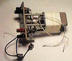  |
A version similar to the circuit below appeared in an electronics magazine almost forty years ago (magazine and author unknown). It has served me well in an old, tiny Heathkit tube-type oscilloscope all these years and is truly a handy gadget.
This version with a single voltage range of about 18 volts peak and a current limit of about 18 milliamps peak. The transformer is an ordinary "filament" transformer or similar with a single secondary. This one-range tracer is quite useful for quick checking of zeners, transistor junctions, LEDs, and most other semiconductors.