
Many people have expressed an interest in the game show timer from the "end user" viewpoint instead of the "hobbyist" viewpoint. These interested folks don't have much electronic assembly experience but they are highly motivated and are willing to give it a try in order to get the end result. It is with these people in mind that the following circuit was developed. This is my favorite and the one I recommend.
Here is a really simple game show timer designed with the beginner in mind! The power source is an ordinary 12 volt lantern battery or battery pack made up of C or D cells. The lamps may be ordinary flashlight bulbs; the prototype uses 750 mA Krypton types (KPR112) with wires soldered directly onto the bulbs. The control devices may be just about any non-sensitive gate SCRs or triacs with a current rating of a few amps. Avoid SCRs that trigger with 100s of microamperes; you want a gate trigger current of a few mA or else you will have trouble with more than one light coming on at once. A low value resistor, perhaps 470 ohms may be added from gate to -12 volts to reduce false triggering.
SCRs are shown and triacs may be substituted by connecting MT1 to the negative battery terminal and MT2 to the lamps. In fact, the two types of devices could probably be mixed if that is what the junk box has to offer! (But not sensitive gate types!) The zener is an ordinary 9 volt, 1 watt type like the 1N4739. The 100 ohm resistor may be any type with a rating of 1/8 watt or more. The reset/power button is an ordinary toggle switch and the pushbuttons are any convenient normally-open type.
The entire circuit may be built into one box with two wires running out to each contestant's pushbutton switch or the SCR, lamp, and switch may be in a remote box for each contestant with three wires running back to the base unit. Many more than three contestants may be added by repeating the pattern.
The following pictures are only to show the wiring for those not familiar with schematics. This prototype is not a good way to build the game!
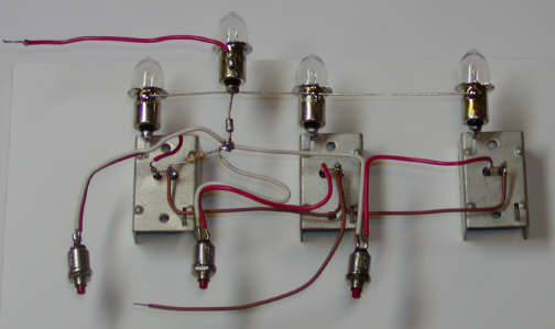
Here is what you see: The three lower lamps are soldered directly to the MT2 terminals of triacs (anodes if SCRs are used). These particular triacs (RCA T2710) come with an integral heat sink connected to MT2. The gate leads (on the left) connect to the pushbuttons (red wires) and the other end of the pushbuttons all go to the resistor-zener junction (white wires). The 100 ohm resistor is the tiny brown part and the zener is the silver part. The brown wires connect the MT1 terminals (cathodes) to the negative battery wire. The red positive battery wire connects to the base unit lamp which is directly connected to the other three bulbs. (Bulb "polarity" is not important.)
A buzzer can be easily added as shown in this photo:
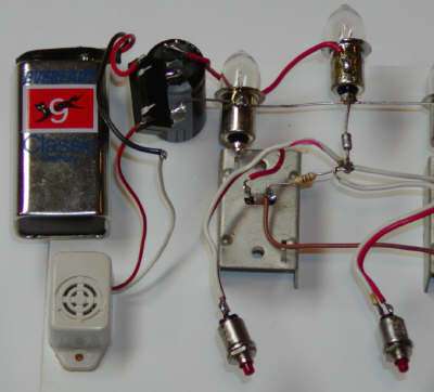
The schematic shows the 2200uF capacitor in series with a 5 or 6 volt reed relay's coil; the larger the capacitor, the longer the buzz. A 9 volt battery is connected in series with the relay's normally-open contacts and a piezo buzzer. The separate battery is highly recommended to prevent electrical noise from the buzzer from triggering the other SCRs. Other battery and buzzer voltages/types will also work.
Here is a somewhat more complex version that uses easily found bipolar transistors. Note that it requires only two wires between stations and base and those wires can be connected anywhere on the "buss". (You can wire each station back to the base unit or "daisy chain" the stations from one to the next with only one set of wires going back to the base unit.)
One base unit and several contestant stations are wired together as shown in the block diagram above.
Most small-signal PNP transistors will substitute for the 2N4403
The NPN power transistor may be just about any type that can handle more current than the bulbs require, perhaps a TIP31. No heat sink is required.
Use 6 volt lamps that consume less than 400 mA. (limited by power transistor gain)
The 9.1 volt zener may be a 1N4739 or similar.
Other voltages should work as long as the lamp voltage is 1/2 the battery voltage and the zener voltage is 3/4 the battery voltage.
The 4.5 volt battery may be changed to match the buzzer's or bell's requirement.
The length of the buzz may be increased by increasing the 10uF capacitor.
The reset button may also serve as the power switch.
The game show timer determines which contestant presses their button first by lighting a lamp and ringing a bell and the slower contestants are locked out. The circuit is convenient in that only two wires are needed to interconnect the stations and the wires may all go back to the base unit or they may be "daisy-chained" between stations. There is no electronic limit on the number of stations. The circuit uses a 24 volt power source and 12 volt lamps when built as shown but the experienced experimenter may scale these voltages along with the zener voltages if desired. If the SCR triggers when the power is applied or when the reset button is pressed, add a 0.1uF capacitor from anode to cathode. (A sudden increase in voltage across some SCRs can trigger them, especially if the gate impedance is high.)
Circuit Operation
When the unit is first turned on, or after the reset button is pressed, all of the SCRs are in the off state. The full 24 volts is present on the two interconnecting wires and when any station button is pressed, the voltage is sufficiently high to trigger the SCR in that station. When the SCR triggers, the contestant’s lamp and the base station lamp light and the voltage on the two interconnecting wires drops to 12 volts. Other stations are locked out at this time since 12 volts is not sufficient to trigger the SCRs.
The buzzer is controlled by a relay and is electrically isolated from the rest of the circuit. When a contestant presses a button, the 680 uF capacitor charges through the relay coil, holding the relay closed for about a second. The length of the buzz may be changed by changing the value of the 680 uF capacitor. Use a capacitor with a voltage rating above 24 volts.
The Scavenger Hunt Game
The game is started by selecting an item to find from a list or deck of cards and the first person to see the item on the TV wins the point. The game winner is the first contestant to reach 10 points. The list should include unambiguous items which are commonly seen on TV programs and the channel may be randomly changed if needed. A contestant that presses the button when the item is not visible on TV looses a point. A TIVO is great for verification!
Using only two CMOS IC packages, this game show buzzer performs well enough to be on TV! The first contestant to press his button locks out the other two contestants. The design is completely asynchronous and "fair". Other logic families will also work and any appropriate power supply is fine. For simplicity, a single-chime doorbell is used for the aural indicator. If a buzzer is preferred, use double pole pushbuttons with the second poles connected to activate the buzzer. Simply connecting a buzzer in place of the doorbell will work but the buzzer will sound until the reset switch is pushed.
Copyright, 1999