
The induction receiver shown below is very sensitive and can serve a variety of purposes. It is excellent for tracing wiring behind walls, receiving audio from an induction transmitter, hearing lightning and other electric discharges, and monitoring a telephone or other device that produces an audio magnetic field ("telephone pickup coil").
The receiving coil could be a "telephone pickup coil" if available or a suitable coil from some other device. The coil in the prototype was salvaged from a surplus 24 volt relay. Actually, two relays were needed since the first was destroyed in the attempt to remove the surrounding metal so that a single solenoid remained. Epoxy putty was used to secure the thin wires and the whole operation was a bit of a challenge. A reed relay coil will give reduced sensitivity but would be much easier to use. The experimentally inclined might try increasing the inductance of a reed relay by replacing the reed switch with soft iron. Avoid shielded inductors or inductors with iron pole pieces designed to concentrate the magnetic field in a small area or confine it completely (as in a relay or transformer) unless you can remove the iron. The resulting coil should be a simple solenoid like wire wrapped around a nail. Don't try to wind your own - it takes too many turns. Evaluate several coils simply by listening. Coils with too little inductance will sound "tinny" with poor low frequency response and other coils will sound muffled, especially larger iron core coils. This prototype was tested with a large 100 mH air core coil with superb results but the 2 inch diameter was just too big for this application.
The other components are not particularly critical. The 2N4401 can be just about any NPN general purpose small-signal transistor. The TL431 is a shunt voltage regulator but it is being used as an audio amplifier in this circuit. In fact, the whole device is nothing more than a low noise, high gain audio amplifier with a pickup coil connected to the input and other amplifiers will work equally well.
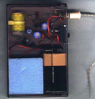
The circuit is built into a 8 mm cassette box with the power switch and earphone jack in the back. The circuit board is a piece of pink countertop laminate which looks good against the violet hue of the cassette box. The battery fits nicely into the box and a piece of foam fills in the remaining space. These video cassette boxes make nice project boxes, unlike audio cassette boxes which are too flimsy.
When you first turn on the unit you will probably hear a lot of buzzing from the wiring in the room. Rotate the receiver in a horizontal plane to find a "null" where the hum is minimal. If you can get a reasonable null, you should be able to hear distant lightning crackles or other magnetic noises. If you cannot get a null then go outside away from the building. Try holding the coil near electronic devices like your computer monitor, telephone (when in use), cell phone readout, etc. You can trace power wires behind a wall or ceiling by listening for a sharp increase in hum as the coil passes near the wire. Make sure that current is flowing in the wires to be traced by turning on a lamp or other appliance. (Here is an experiment to try: Build a line voltage lamp flasher that can be connected to the circuit to be traced. The desired wire will now have an on and off buzz - buzz sound that will be easy to distinguish. I wonder if you could even identify a specific breaker or fuse?)
Other wires can be traced if they are carrying alternating current in the audio range or a signal generator can be connected to produce the current. Connect the generator to the wire to be traced and connect the generator's "ground" to the house wiring ground. Also ground the far end of the wire you are tracing so that current flows in the wire. This ground connection can also just be a temporary wire laying on the floor running from the generator ground to the far end of the wire you wish to trace.
For the ambitious: try wrapping one or two turns of wire around the whole house and connect the loop to the output of an audio power amplifier (one channel of a stereo should work). Add a 4 ohm, high wattage resistor in series to protect the amplifier. You should be able to pick up the magnetic field fairly easily anywhere within the loop with the power amplifier supplying just a few watts of power.