
The Large Inductor Quick Tester is basically an LC oscillator that makes determining the value of large inductors quick and easy. In the spirit of "Battery Toppers", the circuit requires no power switch and may be mounted directly on top of a lantern battery which provides a nice, heavy base.
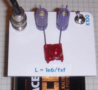
The JFET may be just about any type; the prototype uses a J212. The current diode is a nice way to bias a JFET but they aren't common and a couple of thousand ohm resistor will also work. Measure the voltage across the resistor and select a value that gives about 1 mA. Choose a different FET if you can't get at least 1/2 mA with at least 1k of resistance. If the resistance is too low, the tendency to oscillate will be reduced. Other components aren't critical at all. The .025 uF and 2.5 uF capacitor were selected to make the inductance calculation simple and the values were realized by paralleling standard value film types. The inductance is simply 1,000,000 / (freq squared) for the .025 uF (up to about 1 Hy) and 10,000 / (freq. squared) for the 2.5 uF. Simply hook the output to a frequency counter and measure the frequency with the inductor connected. No current flows without an inductor so no power switch is needed. But, don't forget to remove the inductor! You might wish to install an LED between the plus of the battery and the 10 uF bypass capacitor to let you know when it's drawing power.
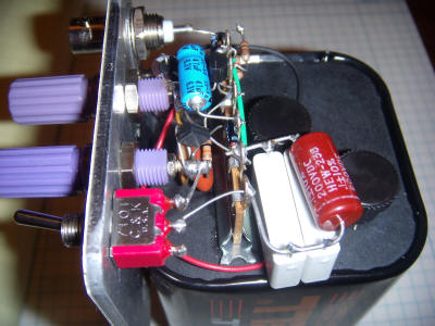
The circuit is built right on top of a lantern battery. Most of the parts are mounted on a terminal strip that is glued to the top of the battery using ordinary contact cement. I 'decanted' contact cement into little squeeze bottles from an economically priced large can and added a little MEK solvent to make it a bit more runny. Just apply a bead to the bottom of the strip, position it so that glue transfers, remove it and let the glue dry a couple of minutes. Then very carefully press the strip into position; you only get one chance to get it right! Contact cement is really fast, plenty strong, and not that difficult to remove when the battery finally dies. The panel is also held by the same glue.
When measuring larger inductors you might discover that the measured inductance is significantly higher than the marked value. Many inductors wound for filtering are measured with a specific current flowing and that current saturates the core, lowering the inductance. This circuit only passes a small DC current through the inductor and the signal is pretty small so the measured inductance will be near the zero current value. The capacitor values aren't exact either, but this quick checker is only intended to give a good estimate of the inductance.
For most accurate results, add a variable resistor or resistance decade box across the inductor and adjust the resistance until the oscillation just starts. Also, remember that the inductance that you calculate is the effective inductance at the frequency of oscillation. Many large inductors have significant capacitance across the winding and that capacitance will cause the inductance to measure higher at higher frequencies. For measuring very large inductance values, increase the 10 uF feedback capacitor to several hundred uF.
![]()