![]()
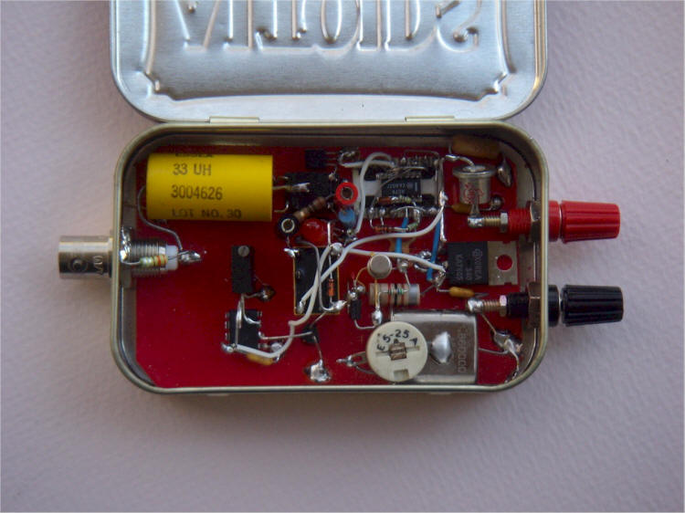
Here's a complete LF Beacon transmitter for LowFER (Low-Frequency Experimental Radio). The transmitter is designed for license-free operation between 160 kHz and 190 kHz, consuming the legal limit of 1 watt power input to the final RF output stage. For fun, the complete transmitter is built into an Altoids mint tin. The circuit is built dead-bug style on a piece of copper clad circuit borad material, lightly painted with Testors transparent Hot Rod Red to prevent tarnish. The paint doesn't seem to make soldering any more difficult. The board is grounded to the tin in a few places.
The circuit features a few unusual techniques. A crystal at 10 times the desired transmit frequency is employed in a PNP oscillator circuit that can directly drive the clock of an 74AC74 flip-flop. The flip-flop has an unusual feedback network that allows it to divide by 5, instead of 2. The two resistors in series with the diodes charge the 180 pF at different rates, changing the state of the D input such that a 60/40 duty-cycle, divide-by-five function is realized. The 180 pF capacitor is selected to give a solid divide-by-five around the desired frequency by temporarily connecting a signal generator in place of the crystal oscillator. Alternately, a variable capacitor could be substituted, and a value found in between the two extremes where the divider ceases to divide by five with the desired input frequency. The values shown should work well near 186 kHz. The second flip-flop in the package is wired as an ordinary divide-by-two, producing out-of-phase outputs for driving the two mosfet transistors.
It's fun to get divide-by-10 functionality out of a dual flip-flop. If you prefer more orthodox approaches, you might choose to divide by 5 with a '161 or similar programmable divider. I still recommend the flip-flop for the divide-by-2 so that the FETs get symmetrical, 50/50 drive. Or you might choose to divide by an even number and use a lower frequency crystal.
The push-pull configuration is very efficient and most of the 1 watt is delivered to the antenna. The voltage on the center-tap (black test point) will be near 10 volts, so the current through the 10 ohm resistor should be about 100 mA, to meet the 1 watt limit. Therefore, the voltage measured across the resistor (black and red test points) should be near 1 volt with a properly tuned antenna. Slight variations in the +12 volt supply can be made to tweak the final power right to the maximum allowed. The values are for driving a 50 ohm antenna.
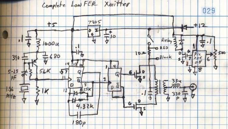
A PicAXE microprocessor generates the on-off keying using a very simple, if not brute force program described below. A relay is used for the keying, but a solid-state switch would also work well. The speed of the keying is set in a somewhat unorthodox manner. A potentiometer applies a variable voltage to one of the analog inputs and the microprocessor measures the voltage to determine the desired rate. This gives the user a simple high-resolution way to vary the keying speed without any additional programming or confusing switches or jumpers.
Don't forget to ground pin 2. (I forgot, as you can see in the photo.) Or, install the 22k and 10k that the manufacturer recommends, and you can program the IC in-circuit.
|
I chose the 1.86 MHz crystal because I stumbled upon a pile of them at a surplus shop. I can supply them for a while. | |
|
The output transformer in the prototype is a center-tapped telecom transformer, typically used in high-speed modems. This particular part is a Pulse Engineering EP6091, but many types will work. The transformer should produce a good fidelity square wave on the secondary and draw little current when no antenna is connected. I have a few of those, too. | |
|
The 33 uH choke and 330 pF capacitor greatly reduces the harmonics that make it to the antenna but it is likely that the antenna has a large resonating inductor that does the same job. These parts will help control the higher harmonics. I have a bunch of the 33 uH chokes, if you want one or two. | |
|
The mosfet transistors are BS170s, but other similar types will work fine. The same part can be used to control the relay, too. I have a nice supply of those. | |
|
The flip-flop is AC, but HC may work fine. The 180 pF capacitor may need to be adjusted as described above. I only have surface-mount versions. | |
|
The two diodes connected to the flip-flop are ordinary silicon types like the 1N4454 or 1N914B. | |
|
Any PNP small-signal transistor should work. I chose a metal can type for looks, but a 2N4403 or 2N3906 would work great. | |
|
The trimmer in series with the crystal allows the frequency to be changed slightly. The value of the trimmer isn't critical and additional capacitance may be connected across the trimmer or an inductor may be added in series to lower the crystal frequency. | |
|
The protection diode in the 12 volt line isn't necessary, if you are careful when connecting power. I used an old-fashioned part just for looks. | |
|
The relay has a 5 volt coil, so it runs on the regulated voltage, but a 12 volt type connected to the input voltage would be fine. I added an LED and 330 ohm resistor in series from the Red terminal to ground, so that I can see when the transmitter is on. I have several relays left. |
Let me know if you have any trouble with obtaining parts. I have most of them "in stock."
The PicAXE program is simple and probably not the way a "real" programmer would do it, but it works fine:
symbol QRSS = w0 'this assigns the name
QRSS to one of the PicAXE variables called w0
main:
READADC 1,QRSS ' this reads the pot voltage to set the keying rate, up to about
QRSS60 at 5 volts
IF QRSS = 0 THEN
QRSS = 1 'set max rate to 1/4 sec ' the rate should not be too fast, so this if
statement limits the speed
ELSE : ENDIF ' if the rate is OK, then leave it as-is and keep going
QRSS = QRSS * 250 'scale to 64000 mS 'this just scales the voltage measurement
to get the desired delay scale
'start character C
HIGH 0 : pause QRSS : pause QRSS : pause QRSS 'three pauses are used for a dash.
Each pause is QRSS milliseconds
LOW 0 : pause QRSS 'this is a space
HIGH 0 : pause QRSS 'one pause is used for a dit
LOW 0 : pause QRSS 'another space
HIGH 0 : pause QRSS : pause QRSS : pause QRSS 'another dash
LOW 0 : pause QRSS 'space again
HIGH 0 : pause QRSS 'end of character C
LOW 0 : pause QRSS : pause QRSS : pause QRSS 'this is the space after the
first character.
'start character V
HIGH 0 : pause QRSS
LOW 0 : pause QRSS
HIGH 0 : pause QRSS
LOW 0 : pause QRSS
HIGH 0 : pause QRSS
LOW 0 : pause QRSS
HIGH 0 : pause QRSS : pause QRSS : pause QRSS 'end of character V
LOW 0 : pause QRSS : pause QRSS : pause QRSS : pause QRSS
pause QRSS : pause QRSS : pause QRSS 'end of call sign has seven pauses to leave
a nice gap before starting over
goto main
That's it. You would change the highs and lows for your particular call. This call is obviously "CV." You would simply copy and paste this program into the picAXE editor and then change the pauses to generate the call you want. The free editor comes with a simulator that makes it easy to see how you're doing. Download the free editor, copy and paste the code above, and give it a try. If the simulation works, all you need to do is hook up the programmer and click on the "program" button.
Do try the free programming editor with the above program. It really is easy to use these things. I'm not a digital guy, so I know the hesitation many of you have. When I got the above simulation working, I clicked on the "program" button to see what the next step would be. A message popped up saying, "done," and I had a working IC in the programming socket! It worked on the first try. In fact, every one I've programmed so far has worked on the first try.
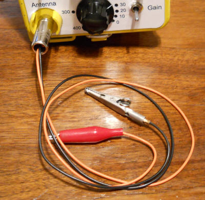
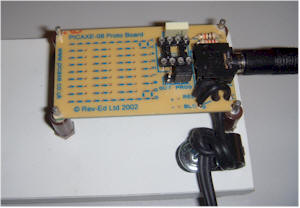
I mounted their little "8-pin proto kit" board on a heavier board and strain-relieved the power supply cord. I used an 8-pin socket, but I can plug in any of the larger processors that have the same power, ground, and programming pins, and just let the other pins hang off the back end of the socket. The black cord on the right is a very inexpensive serial programming cable. This whole setup cost me under $15, including the first IC.
![]()
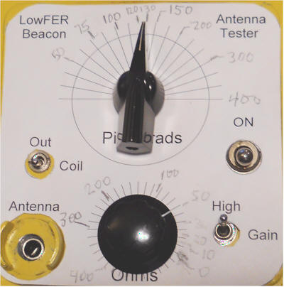
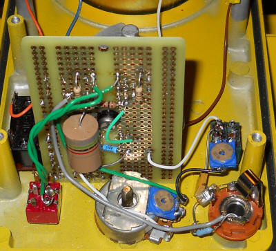
When one builds a legal LowFER antenna, two parameters need to be determined. The total capacitance of the antenna tells the builder what value of inductance is needed for the loading coil. Such coils can be difficult to build so having a good target value makes the task much easier. The other important parameter is the antenna system's resistance. Without the loading coil, this resistance is mainly due to the conductivity of the ground beneath the antenna. These measurements can be made with ordinary test equipment and a simple bridge, but my antenna is going on the rooftop of a large building so I want a portable solution. This bridge measures both parameters for a typical part 15 LowFER antenna, both with and without the loading coil.
The J310 and first 2N4401 form an oscillator that tunes from a little over 100 kHz to about 300 kHz. The oscillation is limited by the 1N914 (or any similar type) and the voltage divider consisting of a 10k and 33k. Those values require the drain to drop several volts below 9 volts before the diode conducts, but the relatively high value resistors don't clip the signal sharply but simply kill the Q of the tank above that signal level. The result is a fairly good sine wave. the 7.5k resistor is selected for good startup at all settings of the capacitor. Selecting a lower value will increase distortion and a higher value might cause oscillation to cease at some settings of the capacitor.
The output stage drives a bridge consisting of a resistor voltage divider for one leg and potentiometers and an inductor for the other. The small 200 ohm trimmer below the main 500 ohm pot cancels the resistance of the fairly low Q 5 mH inductor. The other 200 ohm pot directly below the inductor mimics the inductor's resistance when testing an antenna system that includes a loading coil. Since the resistance of the choke (or resistor) is cancelled by the input trimmer, the circuit can measure down to zero ohms at the antenna test port. In operation, the frequency and resistance are adjusted for a dip in the meter reading which occurs at resonance and when the main pot is set to cancel whatever additional resistance is present in the antenna circuit. A gain switch increases the sensitivity which will be especially useful when checking a complete antenna system. Low gain is used to find the dip then high gain is used to fine tune.
Note the "circuit trick" where I have the high gain switch at the ends of two equal-value resistors. When the switch is open, the gain is low and there's less chance of the long wires causing destabilizing feedback. But when the switch is closed and the gain is much higher, the long wires have little signal because each resistor goes to opposite polarity voltages (the two emitters in the differential amp). So, even though the gain is high, there's little feedback signal radiating from the wires. That's the idea, at least.
The 22 ohm probably isn't necessary. It just seemed to help a little when modeling in LTSpice. I guess it's just compensating for some of the loss in the inductor. The top oscillator section modeled surprisingly well in LTSpice. In the simulation I needed an 8k for a good sine wave and in the prototype it came to 7.5k. I did add resistance to the inductor in the simulation based on a Q measurement of the actual inductor. If you try the simulation but haven't added those transistors, choose similar types. This is a pretty simple yet solid oscillator.
The circuit does exhibit increasing resistance error approaching the extremes of the frequency range due to changes in the Q of the internal choke but it should be plenty accurate for most situations and will provide good relative measurements. Calibrate the ohms dial using a test capacitor near the expected value of the antenna for best results. I used 220 pF and the accuracy is adequate from 100 pF to 400 pF. Careful nulling of the capacitance dial is required to read the resistance accurately, so take your time. The reading should drop to nearly zero.
There is a 150 pF capacitor in series with a 50 ohm resistor connected from the "internal speaker" switch on the 1/4" jack to ground such that the series pair is connected across the output when the plug is removed. This simulated antenna allows for a quick check of the circuit; the meter should dip when the capacitance is set to 150 and the resistance to 50.
Use precision or measured capacitors to calibrate the dial. Set the trim pot directly below the inductor in the schematic to give the correct reading when only a 50 ohm resistor is connected as the antenna (no capacitor). The frequency dial should have little effect.
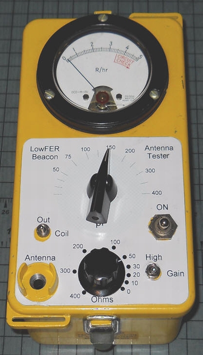
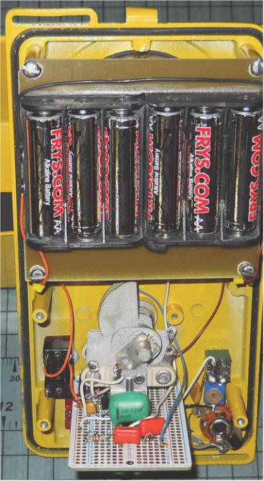
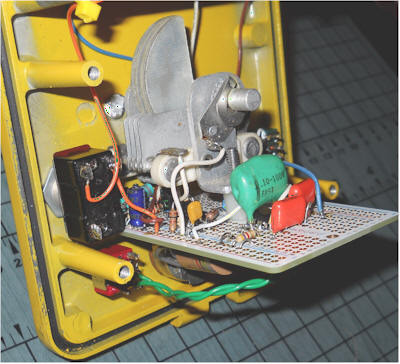
The tester is built into an old CDV715 radiation survey meter. The case is so deep that the batteries can mount above the meter and the prototyping board can stand straight up. I'm pretty fond of these Adafruit prototyping boards. The inventor's idea was to make it easy to transfer a design from a plug-in protoboard to a more permanent form but I think the layout is perfect for projects like this built from scratch. I don't hesitate to stack parts or put parts on both sides and the resulting circuit density is quite good. The plated holes are rugged so modifications are painless.
To calibrate the dials, print out a version (from some sort of cad program) with lots of lines. Then mark the set points with a pencil. Use the markings to determine where to put the final lines for the dial. I just drilled the extra needed holes with a hand drill with no measuring. Then I used a caliper to locate the holes in the cad program (Turbocad). I was off a bit and I could have observed the results and moved the holes in the label slightly. But this project is a "quickie" so I just went with it as-is. It's better than just writing on the face with a marker! I have a box of glossy magazine type paper that I use for the final label and I spray it with Krylon clear coat to protect it. Aerosol glue on the back holds it in position. For a more professional label you can reverse the image and print on overhead transparency film. Then spray on whatever background color you want. I'd then add a coat of aerosol urethane because I've found that the adhesive will dissolve the paint. At any rate, try not to slide the label around when applying it.