
![]()
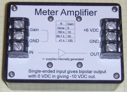
This simple amplifier is useful for boosting small signals up to about +-12 volts. Many low-cost data acquisition devices have full-scale inputs of +- 10 volts which limits their sensitivity, and the negative part of the input range is usually wasted, cutting the available resolution in half. This amplifier runs on 5 to 6 VDC and generates +-15 VDC to power a single, low-power op-amp. The op-amp circuit includes an offset voltage capable of converting a single-ended positive input into a symmetrical bipolar output. Current consumption is low enough to run the amplifier from a lantern battery for over a year of continuous duty (about 1 mA). Switching to a micro-power op-amp will give decades from the same battery. Using a battery allows many experiments to "float," often eliminating ground loop problems encountered when hooking experiments directly to a computer.
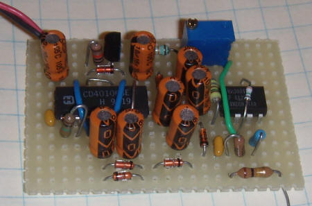
The first gate of the CD40106B hex schmitt trigger is configured as an oscillator and the second gate inverts the output. The other four gates are paralleled in two pairs to proved a Q and /Q drive for a modified Cockcroft-Walton voltage multiplier. The output of the voltage converter drives a low-power op-amp like the LM308, requiring only a few hundred microamps from the 6 volt supply. The voltage converter cannot drive a high-current op-amp. Try a 74HC14 in place of the CD40106 for more current. I just tried one and I get over 4 mA at +-12 volts, plenty for most op-amps.
The LM385-2.5 injects current into the summing node through an adjustable resistor with a value near 1 megohm. A good-quality fixed resistor near 900k and a 200k potentiometer would be a good combination. The zero pot is adjusted to get an output near -10 volts with the input grounded (assuming -10 volts is the negative limit of the data acquisition device - other offsets are possible). The gain will be near 5 with no gain set resistor, and will reach about 100 with a 41k resistor. The zero might vary slightly when the gain is changed. Use a good-quality 3.9 megohm resistor. Lower values may be used for all the gain-setting resistors.
Notes:
|
Not all op-amps can run on +-15 VDC. Many that do draw too much current for this circuit. Choose one that draws less than 1 mA, if possible. | |
|
This circuit cannot drive much more than a typical data logger input. | |
|
Any 1N914B type of diode will work; the current is low. | |
|
it might be possible to run the circuit on the 5 volts from the USB cable when using a data acquisition device. |
Changes:
|
If you choose a different op-amp, you will probably eliminate the 150 pF compensation capacitor and add whatever the new op-amp requires, per the data sheet. Try to select an op-amp with current requirements below 1 mA. | |
|
You might try increasing the frequency of the voltage converter by lowering the .01 uF value on pin 1. Higher frequency will give a little more current. | |
|
The zero offset components, including the LM385 and resistors, may be left out, if a bipolar input voltage is simply to be amplified. You might also decide to offset the output to -9 volts, instead of -10 to give the amplifier a little response below zero volts. That modification only slightly reduces the resolution for a given input voltage span but also gives a little visibility below ground. | |
|
To reduce the ripple from the voltage converter, add an electrolytic directly from pin 7 to pin 4 of the op-amp. Bigger is better, but 47 uF at 50 volts should be enough to drop the ripple below the resolution of the typical inexpensive data acquisition device. To further fight ripple, connect the input ground to the gain set resistor ground as directly as possible, then run a wire from that connection over to the power input ground. | |
|
The 100k and 0.1 uF on the input rolls the frequency response off to about 15 Hz and the 68 pF rolls the amplifier gain off at about 200 Hz. Both can be modified to tailor the response. | |
|
If you want a "hefty" version, hook the gates of a CD4049 in two parallel groups of three and drive them with Q and /Q square waves. Or, use a 74HC14 in place of the CD40106 for more current. | |
|
Or go the other way and shoot for lowest power consumption. My original version used a couple of NPN transistors to generate the two out of phase signals to drive the gates in a CD4069. The unloaded power consumption was about 20 uA! (A two-transistor astable oscillator can be made to draw less power than a linearized gate oscillator.) I hooked that to a micropower op-amp to make a unit that draws only 40 uA when driving a DMM. |