This rain detector will give you a heads-up the instant it starts to rain, hopefully giving you time to close windows and bring in possessions. The battery-powered circuit draws virtually no current when the sensor is dry and the current consumption is low when the buzzer is activated so a couple of AA cells will last a long time. Alternately, a molded power supply with a simple voltage regulator to drop the voltage to 3 volts could be used. The circuit is basically a handy flasher circuit that operates well on only 3 volts using ordinary silicon transistors. When the circuit is triggered, the buzzer is pulsed about once per second for a very short time, giving it a "dripping water" sound which seems appropriate. A slower, longer beep may be had by increasing the 1 uF capacitor. The 10 k resistor may be increased for a longer beep time without decreasing the beep rate but at some point the circuit will cease to function properly, depending on the gain of the transistors.
I
Parts Considerations:
Just about any transistors will work but if you choose to use older, low gain transistors in metal cans just because they are so good looking (like I did), it might be best to try a 4.7 k and 2.2 uF in place of the 10 k and 1 uF. (I had no trouble with a 2N2222 and 2N2906 with the values shown but those are modern types.)
The resistors are not critical at all and any type or size should work fine and reasonable close values are OK although the values shown are quite common.
The 1uF capacitor may be just about any type, with a 16 volt aluminum electrolytic being the most likely choice. The capacitor will see about 1/2 volt reverse bias at times so a 10 volt or higher tantalum capacitor is a better choice; they can handle about 10% of their rating in reverse. A non-polar ceramic capacitor is also a good choice but don't hesitate to use a cheap electrolytic since there is a large resistor in series limiting the reverse current and this isn't exactly a deep space probe!
The 0.1uF is not critical at all and my circuit works just fine without it. It is there in case the buzzer's noise tended to retrigger the circuit.
The switch is any single-pole, single-throw type. My switch, grabbed from the surplus bin, has an unnecessary spring-loaded momentary position, too. I wired it to supply power to the circuit in both positions with the idea that the "test" position is for determining if the sensor has dried sufficiently to turn the circuit back on. Just an excuse to use the switch!
The batteries are just AA alkaline cells with wires directly soldered to the ends for connections. Directly soldering to a battery is a delicate process and I recommend a battery holder for the less experienced solderer. You must make the joint very quickly or the battery will be damaged! Don't dwell on it!
The buzzer is a 1.5 to 3 volt, 15 mA "mini buzzer" purchased at Radio Shack.
The copper-plated nails are available at most hardware stores. Mine are 1.4 mm x 19 mm (3/4").
The circuit is built on perforated circuit board and mounted in a little plastic box:
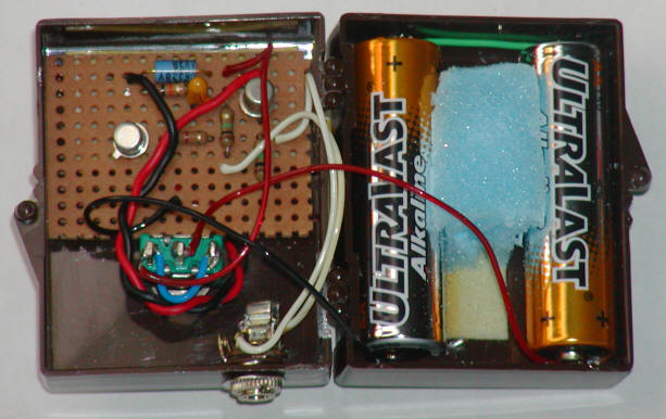
Neither the construction or the components are critical but I do recommend a connector for the sensor to make it easy to work on the box. I used an ordinary 1/8" earphone style connector.
The rain sensor may be built any number of ways and is simply two conductors that are bridged by the rain water. A simple sensor is shown below. Two conductors of bare copper wire are woven through the holes so that the conductors are near each other but do not come into contact. Notice the holes each conductor uses are staggered so the loops underneath miss each other. Ordinary phone cable is used to connect to the electronics.

The sensor above will last a reasonable length of time but a more permanent design is shown below:
 |
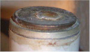
Here it is after 18 months or so:
It's still working fine but showing some |
This probe will cost at least 6 cents! It consists of a penny and nickel sandwiched together with a plastic insulator in the middle. Rain drops bridge the gap between the coins, triggering the circuit. The unit is quite weatherproof and should last for years. Here's how to make it:
First, drill a small hole in the center of a penny just big enough for a copper plated nail to pass through. Solder the head of the nail to the penny with a complete fillet to seal out the rain. Now find a fairly thin sheet of plastic slightly bigger than the penny. Possible sources include the lid from a drink bottle or a lid from a peanut jar. I used a flat section of plastic from a bubble packaged product. (My particular choice was quite thin and the sensor takes a long time to dry out. ) Coat the plastic with spray adhesive and push the nail through, gluing the plastic to the underside of the penny. Once the glue has dried, use scissors to carefully trim the plastic flush with the penny. The goal is to form an insulating washer the exact size of the penny. Now drill a larger hole in the center of a nickel, perhaps 1/4". Wrap the nail with tape to mask it and spray the exposed face of the plastic washer with glue. Stick the nail through the nickel to make a penny, washer, nickel sandwich. Position the penny right in the center of the nickel and let the glue dry.

Once the glue has dried, remove the masking tape from the nail and fill the gap between the nail and the nickel with epoxy. Cut the nail short with a pair of old cutters or the cutter on a pair of pliers (not your best electronic wire cutters) since the core of the nail is steel. To avoid stress on the epoxy, don't hold the nickel as you cut the nail; hold your hand below and catch it as it falls. Solder one conductors of a length of phone wire to the nail and the other to the nickel as shown in the photo. Do not solder the wire to the nickel close to the edge as I did in the photo; that wire had to be moved in toward the center to prevent interference with the housing. Cut an arbitrary length of 1/2" PVC electrical conduit to form the housing; three or four inches is fine. Make sure one end is perfectly flat and straight. Coat that end of the pipe with epoxy and feed the wire through to glue the nickel in position. Once that has cured, turn the assembly over and pour a tablespoon or two of epoxy into the tube to get a really good seal. I decided to shove a few shipping peanuts into the hole to form a plug and poured in more epoxy to get a flush seal so that insects can't build a nest inside and surprise me later. Lead the wire inside the house to the electronics, leaving a hanging loop near the entry point to prevent water from following the wire inside, add a connector and that's it. This probe should be quite weatherproof but it may need an occasional cleaning if debris collects between the edges of the coins.
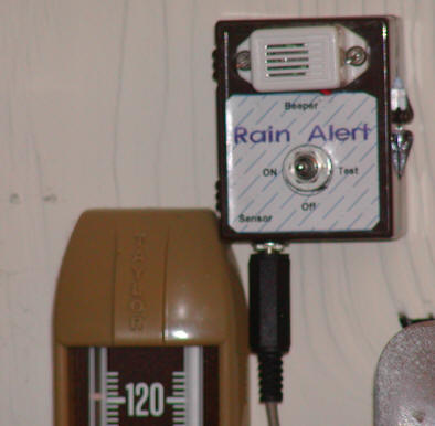
For historical purposes, I include my old design below. The circuit will run the batteries dead if it rains while you are away so a molded power supply is a better choice. For connection to a computer, I recommend replacing the beeper with an optoisolator to protect the computer. The LED in the optoisolator would be connected in series with an appropriate resistor, perhaps 470 ohms and the output transistor of the optoisolator would be connected to a suitable input port with a pull-up resistor to the computer's 5 volt supply. The simple serial port interface might be an interesting starting point. With a similar basic program one pin could be set to provide the voltage for the optoisolator and another pin could read the status.
It may sound silly at first. After all, how hard is it to look outside to see if it is raining. But if you start to pay attention, you will be surprised how often you miss the start of a rain storm. With this simple rain detector, the first few drops of rain will sound the alarm allowing you a few precious seconds to roll up windows and bring in possessions. When used as part of a computer weather data collection system, the exact time of a shower may be recorded. Fig.1 shows a simple rain detector consisting of two strips of aluminum foil glued to a piece of plastic. A single square of foil is glued to the plastic with two lead wires underneath as shown in the figure. The lead wires are striped back so that the foil makes good electrical contact with the conductors but the bare wire should not protrude so that the foil will protect the wire from corrosion.
A narrow zig-zag gap is cut in the foil to electrically separate the two lead wires. The rain drops bridge the gap causing conduction which is sensed by the circuit shown in fig. 2.