
As configured, this continuity beeper emits a tone when the input leads are shorted together. If a resistance is placed between the leads, the tone's pitch is lowered. A 1 ohm difference is audible, and the tone stops entirely at around 150 ohms. There is no tone for semiconductor junctions, even germanium or Schottky. Short-circuit current is under 1 mA, and open-circuit voltage is about 1.5 volts, so damage to external devices is quite unlikely. When the test (input) leads are open-circuited, current drain is under 1 uA, so no power switch is required. Component values are, for the most part, non-critical, and many common low-power transistors should work. It's recommended that the two NPN transistors be fairly well matched.
| BT1 | A76 (SR44) cell |
| C1 | 0.047 uF |
| C2 | 10 uF, 10VDC |
| Q1 | MMBT5087 |
| Q2,Q3 | MMBT5089 |
| Q4 | MMBT2907 |
| R1,R2,R5,R6 | 1.00 kohms |
| R3 | 46.4 kohms |
|
R4 |
100 ohms |
| R7 | 10 kohms |
| T1 | TC001 (Mouser) |
| Spkr. | 8 ohm (Mouser 253-5008) |
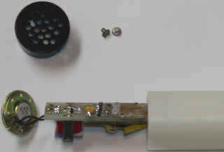
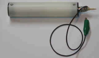
The tone is generated by a blocking oscillator, Q4. Transformer T1 provides feedback and speaker drive. A tiny speaker facilitates mounting the whole circuit in a piece of tubing about 3/4" diameter. The tube acts as a baffle for the speaker, greatly increasing the audible output, and serves to hold a probe tip so the whole circuit acts as a probe.
C1 and R6 set the "on" pulse width. R7 damps the self-resonance of T1 and prevents "stuttering". At the end of a pulse, C1 has charged and must be discharged by Q3 before another pulse will begin. The current in Q3 sets the oscillation frequency. Q2 and Q3 form a modified current mirror whose input current is set by R3, when Q1 is on. Q1 is only on if the input leads are connected across a low value resistance, Rx. The drop across Rx determines the current sharing between Q2 and Q3, with greatest current in Q3 when the drop across Rx is lowest. The current through Rx is mainly through R2 from Q1's base and R1. R4 is larger than R5 so that with Rx = 0, most of the current-mirror current flows in Q3.
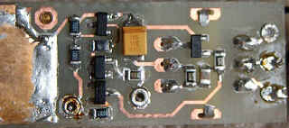
Back of PCB
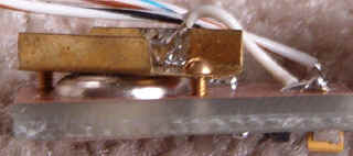
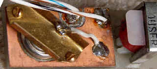
Battery Holder Details
copyright Tom Bruhns, 2003
![]()