
Regenerative receivers provide a surprising level of performance with only a handful of components. They excel at receiving amplitude modulated signals from below the AM broadcast band up to the higher short-wave bands above which the superregenerative detector becomes the better choice. Many designs for regenerative receivers are available and most will do a fine job. The regen is basically an oscillator circuit with a gain control that allows the user to adjust the feedback to a point just below oscillation or, quite often, just above the critical level such that a small oscillation is present. The typical regen uses a tapped coil or additional windings to connect into the tuning tank and the tuning capacitor provides the total tank capacitance. The advantage to this approach is that the tuning range is maximized since there are no fixed capacitors contributing to the tank. The disadvantage is that special, hand-made coils are required. The regens shown below use capacitive taps to achieve the required feedback and, as would be expected, the tuning range is restricted to about two to one. For example, the AM broadcast band would require two inductors to tune, perhaps from 500kHz to 1MHz and 900kHz MHz to 1.8MHz. This disadvantage really isn't all that important when one considers the advantage of being able to use factory-made molded inductors! If a multi-band receiver is constructed, there will be a couple more band switch positions. Actually, the lower tuning range makes fine-tuning a little easier which is critical for achieving the maximum performance.
The basic receiver is shown below. The components are not critical and the values were pretty much the first ones found on the bench that were near the "right" value so don't hesitate to experiment. The transistor could be just about any small-signal NPN including the 2N4401, 2N3904, 2N2222, or others. The audio output is fairly weak and will need an amplifier to drive headphones or a speaker. See the audio amplifier page for suitable amps.
 |
 |
 |
|
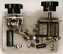
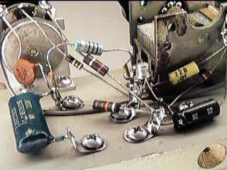
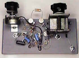
The receiver was constructed on a piece of painted MDF (medium-density fiberboard). This material is great for little projects like this and it is readily available from home improvement stores. Look for the lumber with dull white primer and a very fine "grain". The solder connections were made with solder lugs secured with 1/2" wood screws (see close-up). Predrilling the screw holes is recommended.
The inductor is the highest component in the close-up and it plugs into tiny sockets for experimentation. This inductor could be selected with a double-pole multi-position switch for a multi-band receiver. A 220uHy will tune the lower part of the AM band from about 570kHz to 1.15Mhz, a 5.6uHy will tune from about 3.5MHz to 7.5MHz and a 2.2uH will tune from about 5.6MHz to near 11.6MHz. For calculating inductors, the effective tuning capacitance is from about 85pF to 370pF.
Another receiver was constructed with a single-stage audio amplifier suitable for driving sensitive headphones or a crystal earphone:
 |
 |
The regen control was mounted using an ordinary right-angle bracket from the same home improvement store. Just drill out one of the holes to accommodate the pot. The audio amp. does not show a capacitor on the input because there is already one on the receiver's output. This amp is nothing special and many substitutes are fine.
When the regen control is set too high, there will be a lot of squealing and whistling as the radio is tuned. When it is set too low, there will be no sensitivity. There is no substitute for experience! After a desired station is found, the regen control can be carefully advanced along with careful fine tuning to get the best results. The regen is actually oscillating in this mode but it is synchronized to the signal. In fact, with careful adjustment, a sinewave may be extracted from the collector of the oscillator transistor which is locked to the radio transmitter's frequency. I was able to get about 0.1ppm stability from wwv and from local radio stations! When this poor man's frequency standard looses lock, the speaker squeals out a warning!
![]()
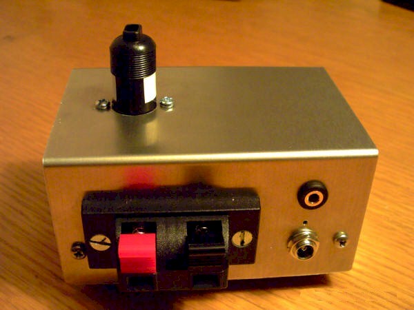
Karen from the U.K. built a work of art:
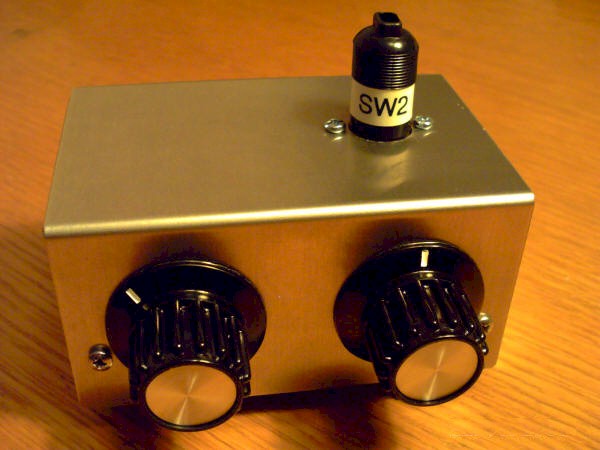
Karen says:
Here are some pics of my completed regen radio!
Things to note:
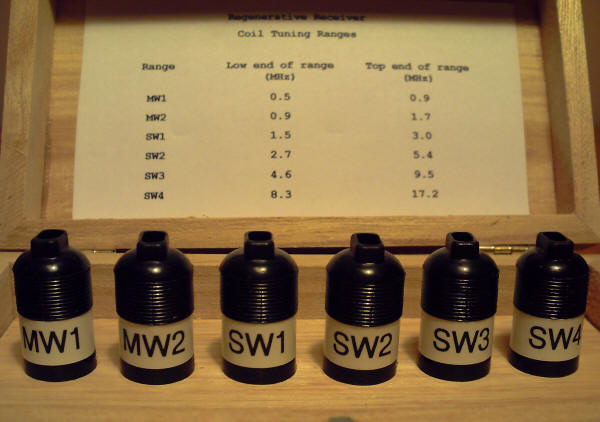
1. Plug-in coils using DIN speaker plugs.
2. Speaker wire clamps for antenna/earth connection.
3. 'Core' RF components built around coil socket (maximises stability).
4. 'Suspended' board bearing non-RF and AF components.
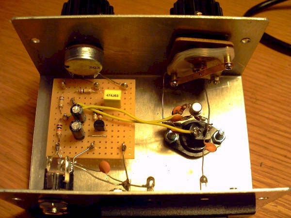
Note too that, even though the stators of the tuning capacitor get their earth
through the shaft/bush/chassis, I still connected the solder tab. If you don't
do this you hear noises due to the poor brass-on-brass contact.
I've used a somewhat higher beta transistor for the audio amp (BC549C) as this
gives a little more volume. I've also put my high impedance headphones as the
collector load. I had to raise the 470k resistors to 1M (which then meant the
1uF between them had to go down to 470n) to keep the collector current down. I
also put 10n across the headphone output otherwise some RF can feed back it
seems.
![]()
Here are some enhancements from Mike:
Thanks for your great TechLib webpages!
I've built your regen receiver and was pleased with its performance. I've added a
few "bells n' whistles" which enhance its ease of use.
Mods include a bandspread cap, a fine regen control, a BCB Trap, and a simple multiband
coil/switch arrangement which allows it to tune most of the SW bands (2.5 - 20 MHz),
using WWV signals at the ends of each band (2.5, 5, 10, 20 MHz) in order to simplify
"calibrating" the tuning cap/coil. An SPDT switch simply selects the proper tap
and shorts out unwanted coil turns for each band.
If you can use any of this info, feel free.
Thanks again, for a fun project.
Mike H.

Thanks Mike!
![]()