
![]()
There are a number of ways to obtain the low voltages required to run small projects from the wall power outlet. The simplest way is to buy a factory-built molded supply which is designed to plug directly into the wall outlet. Some such supplies have an internal voltage regulator and need no additional parts, others provide an unregulated DC voltage and many are simply AC transformers in a box. The regulated types offer less power output for a given size with currents limited to a couple of hundred milliamps but the AC transformer types can provide several amps. The distinct advantage of the molded supply is that no line-voltage wiring is required and they are easy to find in local stores. Some deluxe models have a terminal for the earth ground which may be used to ground the chassis of your project. Such supplies should be grabbed up quickly when spotted at the flea market or in the surplus catalog! Inexpensive computer supplies offer high currents by using switching regulator technology but these supplies often require a fairly high minimum load current (usually on the 5 volt output), so use this type of supply with care.
The unregulated DC supply is a very common type and the simple regulator shown in fig. 1 may be added for projects that require a stable voltage.
Select a molded supply with an output voltage several volts above the desired regulated voltage but remember that the more voltage that the regulator drops, the hotter it will get. A heat sink may be added to the regulator but the regulator's metal tab is connected to the output voltage so insulation may be needed. The voltage set resistor is selected from the following chart.
| Voltage | 1.25 | 1.5 | 3 | 5 | 10 | 12 | 15 | 24 |
| Resistance | 0 | 47 | 300 | 680 | 1.5k | 2k | 2.5k | 4k |
A 5k potentiometer may be used to set the voltage or just to find the optimum value for a fixed resistor. The two most common packages for the LM317 are called TO-220 and TO-202 which have black plastic bodies with metal tab heatsinks. A hole is provided in the metal tab for mounting but this tab is electrically connected to the center pin which is the output pin. The input pin is on the right side and the adjust pin is to the left when the device is held so that the markings may be read (leads down, metal tab to the back):
Fixed regulators such as the LM7812 ( 12 volt) need no resistors and may be mechanically grounded without insulation since the tab is internally connected to ground. Either way, these three-terminal regulators perform well and offer built-in current limit and thermal overload circuitry. Make sure to include the input and output capacitors as shown and mount them fairly near the regulator IC.
To convert an AC molded transformer into an unregulated DC supply, simply add a full-wave bridge and large electrolytic capacitor as shown in fig. 1. The size of the capacitor will depend on the load current and the amount of allowable ripple voltage but a standard 1000uf capacitor with a voltage rating well above the output voltage is a good starting point. Measure the voltage across the capacitor with no load to make sure that its voltage rating is high enough. Here are some equations for selecting the transformer secondary voltage and the filter capacitor:
VRMS = 0.815 (VDC + 1.4) (assumes a full-wave bridge)
C = (DC current max.) /(60 x 2 x Vp-p ) where Vp-p is the ripple voltage under full load.
This equation is for 60 Hz and other frequencies may be accommodated by changing the 60 in the denominator.
The three-terminal regulators can also be used to drop and regulate a battery voltage but remember that the regulators usually need at least a 2 volt drop to regulate properly. (Low drop-out versions needing less than 1 volt drop are available.)
The LM317 can also be used as a current limiter which is handy when experimenting with new circuitry since a simple mistake can lead to disaster if unlimited power is available from the power source. Fig. 2 shows a simple current limiter for the test bench which simply connects in series with the bench power source or battery.
Place the current limiter ahead of the voltage regulator so that the limiter doesn't drop the regulated voltage presented to the load. The 100 ohm pot may be replaced with a fixed value if the adjustment is not needed. The value is selected by:
R = 1.2 / I
With the 100 ohm pot shown, the lowest current setting will be about 12ma. Lower currents will require additional circuitry since the LM317 must supply a minimum amount of load current for proper operation. A voltage regulator may be added after this current limiter to make a current-limiter, variable voltage bench supply.
This current limiter may be made without a heatsink to add a slow foldback feature. When the current limits, the LM317 will become hot and its internal thermal limit circuitry will reduce the current below the set point. The device must cool down before full current will be available again.
![]()
Most hobbyists have accumulated a good-sized box of power adapters (Wall Warts) including simple types that consist of a fused transformer, a bridge rectifier, and a large output filter capacitor. Such supplies should be treated with respect, despite their size, weight and limited output current. The main advantage of using such an old-fashioned supply is that they don't produce significant RFI due to an internal high-frequency switching regulator. Add a low noise, stable voltage regulator and your project will benefit from the quiet supply. Below is the simple schematic of such transformers. The sine generator represents the secondary of the power transformer, the internal resistance is a combination of elements and is a "behavioral" model. The internal capacitor is a large electrolytic, typically in the thousands of microfarads. Just use 1N4002s for the rectifiers. The LTSpice file for the regulator below also includes this circuit.

For a simpler model that's just a DC source in series with a resistor follow these steps:
1) Load the output with a high-value resistor, say 4.7k and measure the output DC voltage; call it Vunloaded.
2) Calculate an equivalent series resistance from: (Vunloaded - Vrated)/Irated where Vrated and Irated are the ratings on the supply's label. For example, I've got a bunch of transformers that output 17 volts unloaded and are rated for 12 volts at 800 mA. I would calculate R= (17- 12)/0.8 = 6.25 ohms. The model is a 17 VDC source with a 6.25 ohm resistor in series.
The full model for Spice is easily generated by following these different steps after step 1:
2) Decrease the load resistance (typically with a power rheostat) until the rated current is reached (should be quite near the rated voltage). Or load the supply with a suitable power resistor value calculated from the output voltage rating divided by the output current rating. Choose a resistor that can handle the power produced by the product of those rating values. For my 12 V, 0.8 amp supplies I'd use a 10 watt, 15 ohm resistor.
3) Measure the p-p voltage ripple with that full load applied. I like a scope for the job but a multimeter will get you close enough; just multiply the RMS reading by 2.8.
The values in the schematic may now be set. The generator's peak voltage is set to 1.5 volts plus the output voltage with the light load in step 1. For example, if your transformer output 17.2 volts in step one the generator would be set to 18.7 volts peak (and set the frequency to your line frequency).
In spice connect a load resistor that is calculated from Rated V/Rated I or use the rheostat's value from step 2. Adjust the internal resistance value to get the rated voltage and current and adjust the capacitance to get the observed ripple. To get you close, at 60 Hz the internal C is close to (0.0125 x DC current) / Vp-p. If your internal resistance is above about 1 ohm you can tweak the voltage up a bit to a better fit to the measurements. That's your model.
My ripple is 1.5 Vp-p at 0.8 amp so the internal capacitance is (0.0125 x 0.8 / 1.5 = 6,600 uF (probably a 6,800 uF).
When reading the DC values in LTSpice choose the middle of the waveform (or control-left click on the current or voltage name at the top of the graph to see the average). Once you know that capacitance you might consider adding another of a similar value in parallel so that when the internal one dries out, your project doesn't care. You can follow this technique with an AC transformer by adding your own bridge rectifier and large capacitor.
The most common failure for such DC supplies is the capacitor losing its capacitance. A simple cure is to add an additional external capacitor calculated as above. This extra capacitance isn't small but it keeps the project working after that unreachable internal capacitor dries out. Most projects aren't taxing the supply to the full current capacity so you can calculate a smaller capacitor for the lighter load, about 1000uF per 100mA of current.
Adding a low-dropout regulator and recommended capacitors will supply a clean output voltage near the rated voltage for current a little under the rating of the transformer. A "12 volt" transformer will supply enough voltage to run a 12 volt, low-dropout regulator at about 80 to 90% of the rated current.
![]()
Here is a feature-filled regulator for 12 volt unregulated linear power adapters. One feature I really like is that the current limit is automatically set by the power adapter itself. When the voltage drops close to 12 volts the power supply is reaching the point where current limit should occur and the 11 volt zener (D3) begins to stop conducting causing the foldback current limit to trigger. Whether it's a 200 mA or 1 amp adapter, the current limit kicks in at 12 volts; perhaps it should be called a voltage drop limiter. (D3 is in series with a base-emitter diode so the voltage where it starts to turn off is near 12 volts.) Foldback keeps the power transistor from overheating if the output is continuously shorted; with my beefy supplies that can be as much as 10 watts. (It seems a shame to have a huge heat sink that only serves a purpose when the output of the regulator is shorted for an extended period.) The foldback point is somewhat modifiable by changing the 82 ohm resistor (R15). A higher value will increase the foldback current level; try values up to about 100 ohms. Too high and your power transistor might get too hot during lasting shorts on the output. If it's too low the circuit may not start, somewhere around 47 ohms. If you don't want current foldback at all leave out R15 and optionally connect a 470 ohm in series with an LED from the left-most transistor's collector to plus for a current limit light (that was my original design). Note: the current limit function runs on current supplied by D2, the start-up zener. If the zener voltage is within a volt or two of the output voltage the current limit circuit may not work. Choose a zener for D2 that is a few volts below the rated voltage of the wall wart supply but a few volts above the unloaded adapter's voltage minus the output voltage. In my case that would be 17 - 12 = 5 so I chose a 9 volt zener, well above that 5 volts and well below 12 volts. (For best noise you want D2 to stop conducting once the voltage comes up so that the regulator circuit is running on its own clean output voltage via R7.)

Another nice feature is that the noise is quite low compared to three-terminal regulators, maybe 10 times lower with the faster response values in parentheses and around 100 times lower with the default values.
Increasing C2 from the fast 0.01uF capacitor to 10 uF (electrolytic with plus to the collector) and changing the faster stabilization network from 68 ohms (R10) and 4700 pF (C2) to a slower 150 ohms and .01uF improves the noise by around 20 dB. But the output transient response is slightly degraded due to the 0.1 ohm (R8) output resistance that is now visible at low frequency. But even with a sudden 100mA load change the voltage will only change 10 mV and then move back to the original value. The regulator's impedance will look like 0.1 ohm for frequencies above a few Hz so feedback along the rail can occur if a high-current AC load is present (the output stage of an audio amplifier, for example). On the other hand, the noise voltage at 10 kHz will drop from about 50 nV/root-Hz to 5 nV/root-Hz. That's pretty quiet! But even at 50 nV/root-Hz this circuit is ten times better than many 3-terminal regulators. So feel free to use the faster values but for most applications I'd use the lower noise option and possibly increase the capacitance directly across the load if there's a high-current AC stage.
Yet another feature is that the 6.8 volt zener (D1) is temperature-compensated by the right-most transistor base-emitter diode. The temp-co resistor may be tweaked to reduce the voltage drift to a few millivolts over a wide temperature range. If you have the patience you can turn your regulator into a high-performance voltage reference. Or just use the values shown for superb voltage stability over temperature and tweak the top resistor to set the voltage. Spice shows 3 mV variation over the commercial temperature range using these standard 1% values but your results will vary a bit more, maybe 10 mV. Just tweak the resistors if you need better.
One more "feature" is that the circuit uses four NPN small-signal transistors ( just about any type will work). So I decided it was an opportunity to use the old MPQ3904 that is four independent transistors in a DIP package (Note: they're not matched on a single substrate but are actually four independent transistors, not that it matters in this application.) The result is an interesting-looking board:
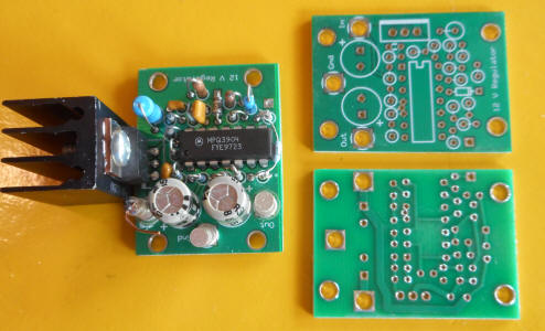
The same layout would accommodate four individual TO92 transistors (collectors on the ends, emitters towards the center, and holes for pins 4 and 11 not used).
Note: The resistor (R15) stretched across the battom of the IC was a modification to add the foldback current limit. That feature and the small heat sink keep the transistor reasonably cool even when the output is shorted for a long time. The change has been made to the LTSpice schematic linked above. The ExpressPCB layout file is included in the zipped folder. I've reduced the terminal holes since my terminals are not that common. Directly soldering wires to the board is fine.
![]()
This simple regulator provides excellent performance when the input voltage is several volts above the output voltage. The simple circuit yields superior noise to a three-terminal regulator; at 100 Hz a 78L05A measured 300 nV/Root-Hz whereas this circuit measured only 30 nV/Root-Hz (20 dB better). The noise at 10kHz drops to only 15 nV and as low as 8nV with the addition of a 47uF across the zener (a 1N750A with R2 =330 ohms). Low voltage zeners are fairly quiet without filtering.
The output voltage is set by the zener and is approximately 0.6 volts above the zener's rating. Select R2 to set the zener current from the following equation:
R2 = 0.6 / Iz
A 600 ohm resistor will give about 1 mA of zener current. Operating the zener below its designed current will yield a lower output voltage. Using a 330 ohm resistor (about 2 mA) with a 1N750 gives an output voltage near 5 volts (instead of the predicted 5.3 volts).
Select R1 for sufficient base current for the pass transistor. A good first cut is found from:
R1 = (Vin - Vout - 0.7)/(0.1 Iout)
A 15 volt regulator powered from 24 volts and supplying 30 mA max. should use:
R1 = (24 - 15 - 0.7)/(0.1 x 0.03)
R1 = 2.8 k
A higher value may be used since this equation assumes a low gain pass transistor. The designer may multiply the value by 3 for most transistors.
![]()
This version uses an N-channel JFET as the pass element to achieve excellent line noise rejection and a bit of short circuit current protection but it is only suitable for light loads. Choose a JFET with sufficiently high Idss to power the load and select R2 as before. The output voltage must be above the pinchoff voltage of the JFET but most JFETs will work if the regulated voltage is above 5 volts.
![]()
When batteries are used to power lower voltage circuits, a switching regulator is desirable to conserve battery life. There are excellent ICs that can do the job with great efficiency and small size. An example is the Maxim (www.maximic.com) MAX639 which converts inputs from 5.5 to 11.5 volts to 5 volts at up to 225mA. The only additional parts are an inductor, schottky rectifier and a couple of capacitors. The following circuit is a discrete switcher similar in power handling capability to the MAX639. The performance is somewhat inferior to the IC switchers but suitable components can be found in most junk boxes.
There are a few component selection considerations:
The input and output capacitors should have a low ESR. Tantalums or special electrolytics intended for switching supplies are recommended. (Extralytic is a trade name for a low ESR aluminum electrolytic.) | |
The pass transistor should have good gain at the maximum load current. The MPS6726 works well at 200mA and a 2N4403 works well up to about 150mA. The first symptom of trouble is that the top of the squarewave at the collector starts to roll off. | |
The 100uH choke can be an ordinary molded type with a DC resistance not more than a couple of ohms. The circuit works with a fairly wide range of values. | |
The 1N5818 may be just about any schottky rectifier since both the voltage and current are low. |
The efficiency is about 80% at 200mA and drops to about 75% at 100mA due to the quiescent circuit current. The effect on battery life can be significant since small batteries are more efficient at lower discharge rates.
An example of an application is a homemade medical thermometer that uses a 3 1/2 digit LED panel meter as the readout. The meter draws about 120mA most of the time and the switcher lowers this current drain to about 80mA from a 9 volt battery. Current drain would be less for a higher voltage battery. The circuit was built on a small piece of perf board with many of the parts standing up for maximum density:

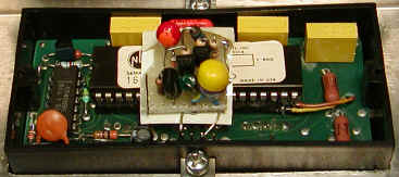
The top of the molded choke can be seen between the large yellow capacitor and the black transistor.
![]()
Did you ever install one of those low-cost LCD panel meters in a project only to discover that it requires a floating power supply? I just did! The meter cannot share a DC ground with the voltage to be measured. The above circuit came to the rescue. It draws about 4 or 5 mA from the 9 volt supply and can supply up to 2 mA at 9 volts to the LCD meter or other load but the two capacitors isolate the grounds. Works like a champ! Also see Craig's regulated version.
![]()