
Occasionally a designer needs a dual power supply to power a circuit that is operating with signals near or at ground but the only available supply is a single polarity, usually positive. Many excellent IC solutions are available but a suitable solution for many projects may be constructed from "junk box" parts. The simple circuit below will generate about 9 volts and -4 volts from a single 5 volt supply with sufficient current to power a simple op-amp circuit. The positive voltage drops to about 7 volts when supplying 7 mA and the negative voltage drops to about 3.5 volts when supplying 3.5 mA (1k loads). Although this isn't exactly a +- 15 volt supply, this is plenty of voltage and current for many op-amp circuits and will allow the output of most op-amps to swing below zero volts and will allow most op-amp inputs to measure voltages below zero volts. This circuit uses the CD4049 which is a high current version of the CD4069 which will also work with somewhat lower current capability.
The two inverters on the left generate a square wave and the other four inverters are connected in parallel to increase the current drive to the diodes. The diode on top clamps the voltage on the top capacitor at about 4.5 volts when the inverters go low. When the inverters go high, their output voltage is added to the 4.5 volts to give about 9.5 volts. The second diode rectifies this voltage to give a little over 9 volts on the output. The bottom two diodes work in the same way only the voltage on the first capacitor is clamped to about 0.5 volts on the positive swing and then goes down to about -4.5 volts on the negative swing of the inverters, giving about -4 volts out.
The prototype is operating at only 500 Hz to allow for the use of some old-fashioned germanium rectifiers that I have in large numbers. If more modern schottky rectifiers are used the frequency may be set higher by lowering the .001uF capacitor or the 1 megohm resistors. The 4, 330 uF capacitors are larger than necessary and a few uF will suffice if the frequency is raised to, say, 5 kHz (try 100k resistors or a 100pF capacitor). Yep, I have a lot of those 330 uF capacitors, too. In fact, I have a few thousand of the CD4049, if you would like a few. (charles@wenzel.com)
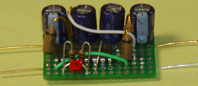
This little circuit is going into a sub-picoampere leakage meter for characterizing JFETs and other components for extremely high impedance circuits.
![]()
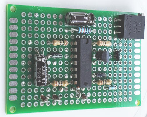
When there's plenty of voltage from the single power supply a simple synthetic ground will do the trick. Craig shows how to use a simple audio amplifier IC to generate a ground at V/2. But other voltages may be handy, too. For example, the circuit below uses an ordinary LM324 quad op-amp to generate a precision +5 VDC and approximately +9 VDC and -3 VDC from a 12 volt supply (for powering a special amplifier for an RTD). The 5 volts is quite precise and the-3 volts represents what's "left over" after allowing for plenty of headroom for op-amps (4 volts above the precision 5 volt reference voltage). That negative voltage will allow most op-amps to work below zero volts a bit. (In the RTD application a summing amplifier output must swing to about -50 millivolts.) The quad op-amp will supply nearly 50 mA at 5 volts thanks to the paralleling of two amps for both the 5 volts and the synthetic ground, plenty of current for many projects. For projects needing 20 mA or less, an LM358 dual op-amp could replace the LM324. The 10 ohm resistors aren't needed in that version.
![]()
Another more robust way to accomplish the same result is to use a high-current buffer like the old LM6325 to generate the ground and then use ordinary regulators to produce the desired voltages. Two low-dropout regulators can generate +-5VDC from +12 volts:
Note: I haven't built the above circuit with the LM6325 yet so it's untested at this point.
With the LM6325 connect pins 3,4,5 and 10,11,12 to as large a heat sink as is practical on the PCB (ground plane, for example) if the power dissipation is to be over a watt. DIP14 heat sinks also help.
The 10k voltage divider could be modified for applications needing unbalanced voltages. It's not uncommon to need only a volt or two negative for using non-single-supply op-amps, wanting the rest for maximum positive swing. If the circuit only powers op-amps and/or the 12 volts is well-regulated the regulators would not be needed.