
The simple transistor spot checker is one of the most handy gadgets on the experimenter's workbench, especially if said experimenter has numerous surplus transistors with unknown histories or mysterious "in-house" part numbers. A quick check can confirm that the problem lies elsewhere when a new circuit fails to function properly or help jog the memory on whether a 2N2905 is NPN or PNP without a trip to the data book. The following schematic is of a tester I made about 30 years ago. (Yes, they had transistors back then.)
 |
 |
The transformer is a miniature type that was used for interstage coupling in transistor radios and it has enough series resistance to limit the transistor current to about 30 mA. The earphone was commonly used for toy "crystal" radios and it serves as an effective speaker with the earpiece removed. The neon lamp limits the voltage swing across the transistor and lights up brightly for a "strong" transistor. The switch has a center off position although the circuit will not draw current without a transistor plugged in. Operation is simple: The transistor is installed and the 100k pot is turned to attempt to get an oscillation in one of the two switch positions.
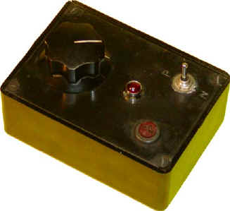
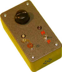
A modern version of the spot checker is shown below:
It features parts more easily found today:
The transformer is a 1:1, 600 ohm audio transformer used for telephone line isolation. A center-tap is made by connecting one winding to the other but the phasing is important. If your tester doesn't work, try reversing the connections to one of the windings. | |
The speaker is from a discarded headset for a modern radio or audio player. It should measure a few tens of ohms at least but not more than 100 ohms. | |
The neon lamp is replaced by a bi-color LED which is just two different color LEDs in one package. The color changes as the intensity of oscillation varies making it easier to distinguish between different types of transistors. |
A significant difference between this circuit and the earlier version is the resistor between the base and emitter. This resistor makes it necessary to turn off the power even when no transistor is installed but it also gives the tester greater utility. It may be left out if only ordinary bipolar transistors will be checked. By including it, the tester will work with a wide variety of semiconductors:
NPN or PNP bipolars: install transistor, switch to NPN or PNP, turn knob until oscillation is achieved. | |
NPN or PNP darlington bipolars: same as above, but knob setting will be near the higher resistance end. | |
VMOS FETs: N-channel will behave like NPN and P-channel will behave like PNP. | |
SCR: Install gate to base, anode to collector, cathode to emitter and select NPN. Starting with the pot in the highest resistance position, slowly turn the pot down until the power LED suddenly lights indicating triggering. The tester can only supply a few mA of gate current so very high current SCRs may not trigger in this tester. | |
JFET: Don't plug in the gate lead! Drain and source go the collector and emitter. Turn on unit and touch the gate lead with your finger. "Hum" should be heard in the speaker if the JFET is good. The volume will depend upon the local field intensity and if the field is large enough, the lights will vary, too. | |
Diodes: plug into collector and emitter. Power LED should light in only one switch position. | |
LEDs: plug into collector and emitter. LED will light in one switch position. IR LEDs will act like diodes but will not light (obviously). |
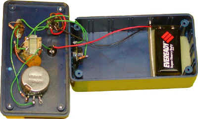
Construction
The circuit is simple enough that point-to-point wiring is sufficient. The transformer is glued onto the back side of the front panel, the speaker is glued over a few holes in the bottom side and hookup wire makes the connections:
 |
 |
Note that the 1uF capacitor in not really present in either tester even though good design practice would recommend it.
By the way, watch out for some DPDT switches! Some of these switches short the two center terminals together when in the off position so don't connect the battery here. The center two terminals should go to the circuit and the battery connects to the outer terminals as is shown in the schematic.
The cheap blue plastic look of the inexpensive enclosure is quite effectively covered by "hammer" look spray paint. This paint is available in art stores and is similar to the gray "hammertone" paint used on factory painted metal boxes
![]()