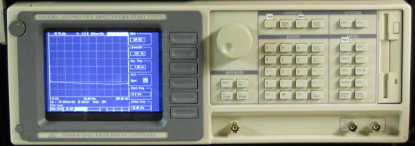
I had three Stanford Research SR760 FFT Spectrum Analyzers with bad CRTs so I embarked on an effort to replace the CRTs with something a bit more modern. The first step was to generate composite video from the available signals:
In the connector drawing above, the 560k should be shown as connecting to +5 VDC. That leads off to the brightness control on the front panel.
It works great so I made these boards:
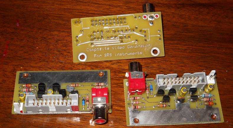
By the way, I have six more of these (tested) that I'll sell for $20 each. Believe me, that's less than I have in them if you paid me minimum wage. I'll put them on eBay for a "buy it now" price if you request.
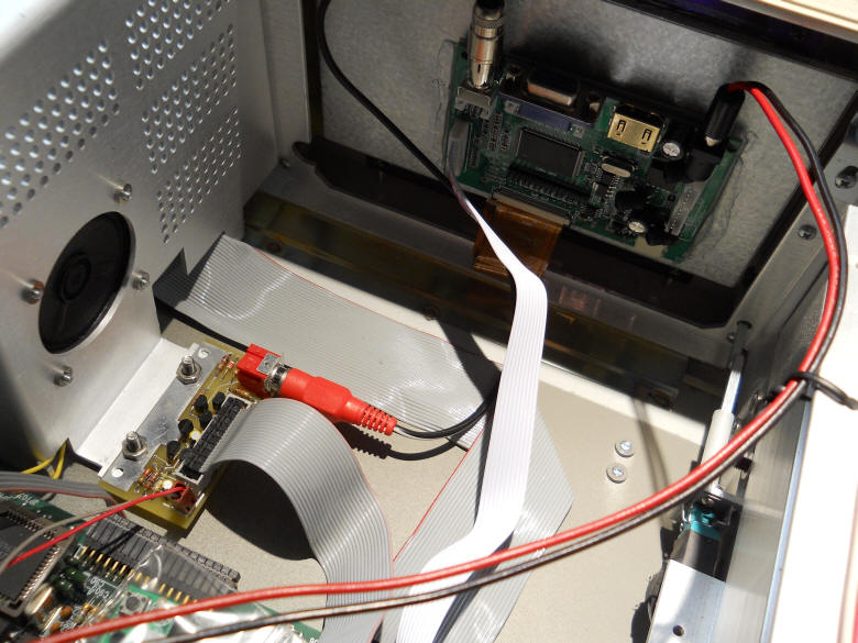
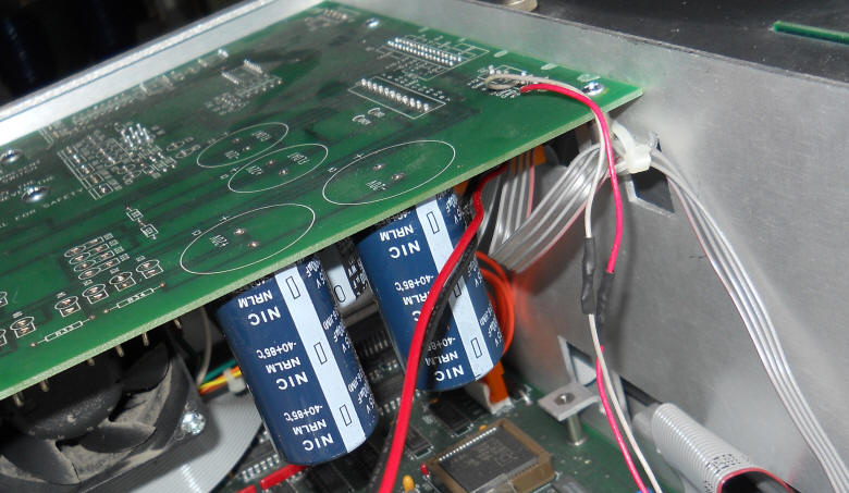
To remove the old CRT both of the large boards directly behind it must be loose - remove the screws holding them down. Once the CRT is out, open the appropriate access panel, unplug the ribbon cable and cut the power wires. Find a suitable place to mount the little composite video board. ( I drilled a couple of additional holes in the strip of ground plane on my PCB and mounted it below the speaker. If I ever remake these boards I'll move the holes. My board is on the left in the image below (with the red phono connector plugged in). Note the red line on the ribbon cable corresponds to the red paint on the connector.
I used a 7" HDMI display that claims 800 x 480 for NTSC video. Make sure to select one that has the RCA video connector and says "NTSC." The video is only 640 wide so you will have dark bands on each end where the display extends past the bezel - perfect! You can see how nicely the image nearly fills the screen below.
I hesitate to admit how I fastened the new LCD to the front plastic window - I used glue around the edges, right onto the plastic. : ) But it's pretty solid so I'm happy.
The little video board has a molex connector for +5 volts and the LCD runs on +12 volts, both available on the power supply.
This time I used the existing power cable for the CRT to run the LCD and I soldered a couple of wires for the +5 VDC.
Use the LCD's contols to set the contrast to maximum and play with the other controls for the best image. I unplugged and sealed that little control panel for the LCD in a plastic bag and taped it to the inside of the chassis in case it's needed in the future.
But there's a catch. It seems that SRS uses more than 480 horizontal lines so you will lose just a bit of the image. Use the soft key controls to position the display to where the top of the screen just barely shows all the lines needed to display the numbers. You will lose a few lines at the bottom. For my applications it means I can't see the number of averages and I can't read "overload." But that's okay because the flashing "overload" box is still visible as a flashing white line...good enough for me!
But wait! Reader Gaston discovered that using the Swees Model AV-HDMI-B AV to HDMI converter nearly eliminates the problem. Feed the video into this converter and the output of this converter to the new LCD display via a short HDMI cable and you get all but one line and that line is just the outline on either the top or bottom. Make sure to get the one that looks like this:
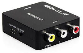
Cut the USB cable and connect the red wire to +5 and the black wire to ground. I've tried an identical-looking converter with bad results (actually fewer lines display than when using the composite video) so try to find this exact model, possibly on eBay.
Also, this composite video signal works wonderfully with other CRTs including a large one I have. So you could bring this signal out the back and use a larger display. The circuit should have no trouble driving two displays. Here's what one of mine looks like:
Good enough for government work, I'd say.