Charles Wenzel
The following circuit is constructed on a Schmartboard 201-0001-01.
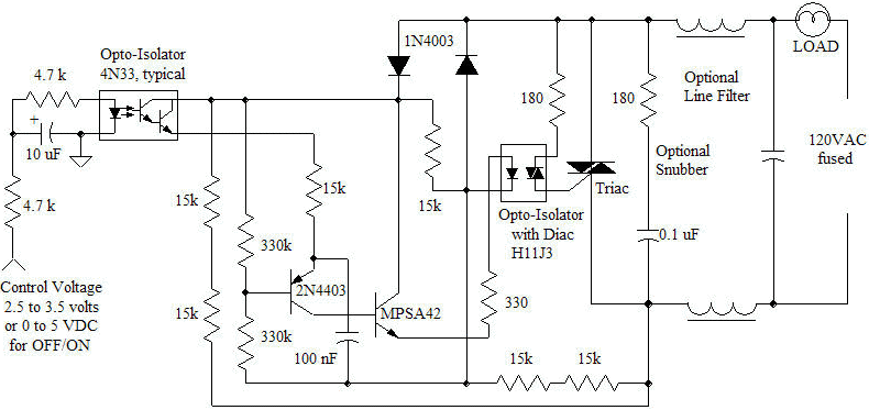
This line voltage power controller interfaces a DC control voltage or microprocessor logic output to an AC load. By adding a filter capacitor to the input resistors, the circuit may be controlled by a duty-cycle modulated square wave with about 2.5 volts average giving minimum brightness and 3.5 volts average giving full brightness.
This circuit has some distinct advantages over simpler "dimmers". The two-transistor pulse generator completely discharges the timing capacitor after each trigger pulse and before the next half-cycle begins, completely eliminating hysteresis and start-up problems. In dimmer mode, the circuit will readily start up at the dimmest setting without any overshoot or dead zone. Since the pulse generator starts fresh at the beginning of each new half-cycle of the line voltage, the used could conceivably change the amount of each half-cycle applied to the load from one half-cycle to the next with a microcontroller synced to the line voltage. (The 10 uF duty-cycle filter shown in the schematic would be removed for such quick control.) A simple on-off control is had by applying a logic signal to the input resistor but the velvet-smooth control in dimming mode makes flicker-free yet fast response possible for applications like color light shows (color organs), large pixel displays or smooth faders for sophisticated lighting systems. The instant cycle-to-cycle response would be useful in feedback-type motor speed control applications, too.
The schematic above features a diac optical isolator to trigger the triac but the single-polarity pulse is also suitable for driving a pulse transformer like the Vishay/Dale PT-50-102 or the Sprague 66Z906 as shown in the inset below. A layout could accommodate both options. Ordinary 1/4 watt resistors are used throughout but the two pair of series 15k resistors could be replaced by single 30k, 1/2 watt resistors. The triac in the prototype is a T2800D (8 amp, 400 volt) but any number of types will work fine since the triac isolator provides a hefty trigger current pulse. The prototype in the photo below includes a heatsink on the triac but the part runs cool with the relatively low power 60 watt bulb as a load. The dimmer is at a fairly low setting in the photo and a typical pulse transformer is shown right above the prototype board.
A 220 volt version is simply realized by increasing the two pairs of series 15k resistors up to a total of 60k each. Provisions for four 15k resistors in each spot would simplify parts procurement. Additionally, the 180 ohm in series with the diac optoisolator should be increased to 360 ohms.
In lower power applications, the diac in the optoisolator could run the load directly. A layout could include provisions for a snubber network consisting of a series resistor and line voltage rated capacitor, typically 0.1 uF. The board could also have provisions for a couple of line chokes or a common/differential mode transformer and another line voltage rated capacitor to form a line filter to prevent harmonics generated by the triac from getting back out on the line. These parts are not needed for most prototyping, however.

The two 1N4003 rectifiers rectify the line voltage and provide a positive voltage to the two-transistor pulse circuit for each half-cycle of the line voltage. As the voltage rises the 100 nF timing capacitor begins to charge through the 15k resistor and opto-isolator. (When the line voltage is sufficiently high, a bit of charging current also comes through the PNP base-emitter zener.) When the voltage on the emitter of the PNP exceeds the voltage on the base, set by the two 330 k resistors, the transistor conducts. (Note that both voltages are increasing as the cycle proceeds but the emitter catches up to the base.) The MPSA42 also conducts, reducing the voltage on the base of the 2N4403, causing the two transistors to snap on in a regenerative manner. The 100 nF capacitor quickly discharges through the 330 ohm resistor and the LED in the diac optoisolator, triggering the diac and triac. The current is limited to just under the rating of the LED at the peak of the line voltage by the 330 ohm resistor. The regenerative action keeps the two transistors on until the capacitor discharges to a very low voltage and the circuit resets quickly due to a reverse regenerative process. The amount of time it takes the capacitor to charge and trigger the triac is determined by the optoisolator darlington. Higher current flowing in the darlington causes the trigger to occur earlier in the cycle, applying more of the cycle to the load. The darlington optoisolator could be replaced by a 200k pot with an insulated shaft for a simple mechanical lamp dimmer free from the annoying start-up problems most inexpensive commercial lamp dimmers exhibit.
The circuit was built on a Schamrtboard 201-0001-01. The parts are more crowded than necessary to allow room for future experimentation. The higher density required a few strategic jumpers (blue wires and a few component leads on the bottom.

| Component | Value | Quantity | Notes |
| Schmartboard | 201-0001-01 | 1 | Prototype will be built with leaded parts. |
| Diode | 1N4003 | 2 | Most rectifiers with sufficient breakdown voltage are fine. |
| Capacitor | 100 nF, 50 volt | 1 | Ceramic or film type; not critical. |
| Capacitor | 10 uF, 16 volt | 1 | Optional cap for duty-cycle averaging. |
| Opto-Isolator | 4N33 | 1 | Darlington output type. |
| Opto-Isolator | H11J3 | 1 | Diac output type. |
| Resistor | 180 ohm | 1 | 1/4 watt carbon film. |
| Resistor | 330 ohm | 1 | 1/4 watt carbon film. |
| Resistor | 5 k ohm | 2 | 1/4 watt carbon film. |
| Resistor | 15 k ohm | 6 | 1/4 watt carbon film. |
| Resistor | 330 k ohm | 2 | 1/4 watt carbon film. |
| Triac | T2800D | 1 | Many ordinary triacs will suffice. |
| Component | Value | Quantity | Notes |
| Pulse Transformer | PT-50-102 | 1 | Used in place of the H11J3 optoisolator |
| Capacitor | 0.1 uF | 2 | Line voltage grade. |
| Resistor | 180 ohms | 1 | 1/4 watt carbon film. |
| Inductors or Line Choke | 25 mH, typical | 1 (or 2 if individual coils) | Typical combination part: Coilcraft P3717-A |
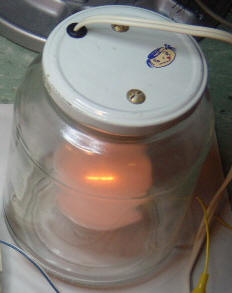
A bulb mounted inside a pickle jar (left) makes for a relatively
safe test load although it will get hot if left running for long periods. The
photo shows the dimmer running at a low setting and the circuit has no trouble
coming back on to this level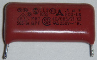 when the power is cycled with no "flash" overshoot or startup issues.
The line filter and snubber are optional parts that might be needed in a particular design but can often be left out for prototyping. Here is a typical bypass capacitor with all the approvals that would typically be added to a final product design along with chokes to prevent EMI. Such parts are found in common PC power supplies right before the line-voltage rectifier.