
(See "Fun with Ionization
Chambers" for more chamber ideas.)
This simple radiation detector uses a PicAXE-08M microprocessor to measure the voltage drift rate on an ionization chamber's sense wire, eliminating the need for a high-value resistor. An electrometer-grade JFET is used to buffer the voltage on a sense wire inside the chamber, and a PicAXE microprocessor measures the rate of change of that voltage, periodically discharging the wire through the JFET's gate-source junction. This unorthodox way of discharging the ion chamber wire eliminates the need for a special, low-leakage switch, and takes advantage of the PicAXE's ability to use the same pin as an analog input or a digital output. Choose a PN4118 or PN4119 (or 2N equivalents) jfet.
The ionization chamber and JFET circuit must be constructed with some care. The internal wire must be extremely well insulated from the can and most insulating materials are inadequate. I recommend styrene necklace beads:
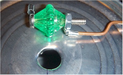
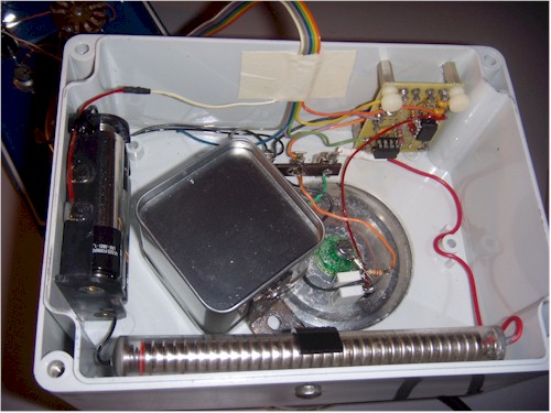
This large bead has a hole large enough for a 4-40 bolt that holds standoffs for the chamber's center wire, and for connection to the JFET gate. The can is heated and the bead is pressed into the hole, melting into place as it seats. With a little effort, the bead will be locked into the hole, once the metal cools. You may add epoxy to hold the bead, but keep the epoxy away from the conductors. Make sure to cut the copper center conductor (just a piece of 14 AWG solid copper wire) about a half inch short of the can opening, so that the foil window won't accidentally touch it. Choose a can about 4.5 inches tall, with a diameter of about 4 inches. The JFET is mounted on the outside, bottom of the can as seen below. The can is mounted to a project case, and a large hole exposes most of the bottom of the can.
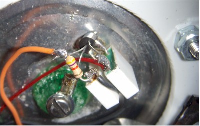
The two white blocks are low-value capacitors with at least a 100 volt rating and they are simply there to support the parts, and are not shown in the schematic. Ordinary insulated standoffs or a terminal strip will also work, but make sure the gate wire doesn't touch them (or anything but the solder terminal on the plastic insulator). Connect a non-polar 1 uF from the positive supply and the chamber can, if these aren't used. The value isn't critical, but make sure the voltage rating is well above the voltage on the chamber can. An electrolytic will also work, but make sure to connect the positive terminal to the can.
I know it's hard to believe, but I had to make sure that the red insulated wire didn't accidentally touch the gate lead. I should have routed it differently. Ordinary PVC insulation leaks too much! Many readers have had troubles with these chambers because they simply don't believe that "insulators" leak, but they do!
The circuit may be constructed in a simpler way than this prototype, but it is important to have a shield over the JFET and resistor. Simply tack-soldering a little mint can over those parts is sufficient. But don't leave the shield out. In the photo below, the shield can is positioned off to the side to expose the JFET for viewing. It is held in place by a bracket soldered to the shield can and mounted on one of the bolts holding the chamber to the case. The long battery pack is a homemade 50 volt battery made from surplus alkaline cells, but three or four 9 volt rectangular batteries will work fine. There is virtually no current drawn from the high voltage section, so no switch is needed. Feel free to use one of the various high-voltage generators I used in the other ionization chamber projects, too.
I used the older CA3160 op-amp as a meter driver, but any low-voltage "rail-to-rail" op-amp will work.
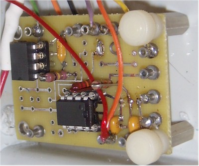
I used my own prototyping board for the PIC, but any construction technique is fine. The two yellow capacitors are left-overs from an unnecessary voltage regulator.
Here's how it works:
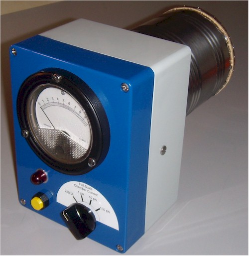
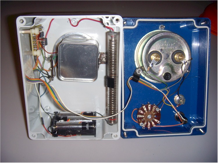
Positive ions in the chamber produced by radiation are attracted to the center wire, where they steal electrons on contact. That process produces a positive current that charges the capacitance of the wire and JFET gate in a ramp fashion. The JFET's source follows the gate voltage (with about 1 volt of positive offset), and the PIC measures the rate that voltage changes. The PIC first resets the chamber by momentarily pulling the source of the JFET to ground. The chamber wire discharges through the gate diode to within a few hundred millivolts of ground. Then the PIC releases the source and measures the voltage. It waits a fixed amount of time and makes another measurement. The two measurements are used to calculate how fast the voltage is changing, and, therefore, how much radiation is striking the chamber. The process automatically repeats, flashing the LED each time. The value to display is output as a variable duty-cycle pulse that is filtered and buffered to drive a meter. I chose an old-fashioned analog current meter, but other meters will also work. The PIC may be programmed to send the data back to a computer via the serial port, too.
The four-position switch selects one of four voltages to send to the PIC to select the range. The most sensitive range is about 250 fA, full-scale, and that was experimentally determined by connecting a high-value resistor to the chamber wire and calculating the rate of change of voltage to determine the capacitance (about 10 pF). It's an approximation, but relative readings are usually all that's interesting. If you build you chamber like this one, the capacitance will be quite similar. The less sensitive ranges are 1, 10 and 100 pA. It takes 10 seconds per reading on the most sensitive scale and only a fraction of a second on the least sensitive scale.
View a short clip with the meter on the 1 pA scale, detecting a thoriated lantern mantle. Note the delay as the PIC measures the rate of voltage drift (about 5 seconds on the 1 pA scale).
The program is quite simple and short, leaving lots of room for modifications and additional features:
main:
high 0 'turn on LED.
w4=10000 ' set delay to 10 seconds.
w5=8 ' set multiplier to 8 (increases reading by 8). These set the 250 fA scale.
readadc 1,w3 ' read the 4-position switch voltage (will be near 0, 85, 171, or
256).
if w3 >40 then ' see if switch is above first position.
w4=5000 ' set delay to 5 seconds.
w5=4 ' set divisor to 4 (these two mods reduce the sensitivity by 4 for the 1 pA
scale.
endif
if w3 > 125 then ' see if switch is above second position.
w4=1000 ' set delay to 1 second.
w5=2 ' set multiplier to 2 (reduces the sensitivity by 10 for 10 pA scale).
endif
if w3 > 210 then ' see if switch is in fourth position.
w4=100 ' set the delay to 100 milliseconds.
w5=2 ' set multiplier to 2 (reduces the sensitivity by 10 again for the 100 pA
scale).
endif
low 4 ' pull the source of the JFET low
pause 300 ' keep it low for 300 milliseconds.
let dirs = %00000100 ' set the necessary pins back to inputs.
pause 50 ' let the voltage stabilize.
low 0 'turn off LED
readadc10 4,w0 ' read the JFET source voltage.
pause w4 ' wait for the selected delay time.
readadc10 4,w1 ' read the JFET source voltage again.
w2 = w1-w0 ' calculate how much the source voltage changed during the delay
w2=w2*w5 ' scale the result by the selected multiplier.
if w2>1000 then ' sometimes the voltage will drift negative, causing a
full-scale reading.
w2 = 0 ' these commands reset the meter to read zero when that happens.
else
endif
If w0>512 then
w2=800 'peg the meter because the first reading shouldn't be so high - must be
lots of radiation
endif
if w2 > 800 then ' My meter pegs at about 700, so this limits the current a
little higher.
w2 = 800
else
endif
pwmout 2,off 'reset the pwm from last pass.
pwmout pwmdiv4, 2, 249, w2 ' set the pwm output for driving the meter.
goto main ' wash, rinse, repeat.
' There's plenty of room for more of a program, if desired.
' Copy all this text, paste it into the editor, and click on "syntax" to check
it.
![]()