
This page started as a warning to VLF/LF enthusiasts of the new "smart' power meters that produce a lot of low frequency RF noise. The effort to subdue that noise has led to a host of improvements that might apply to your setup.
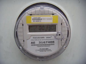
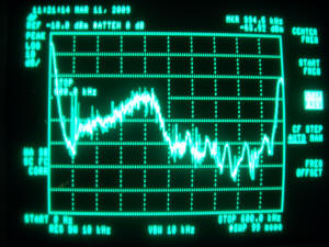
The new meter that got the ball rolling is shown below, next to the RF spectrum it generates. The plot is from zero to 600 kHz and you can make out KLBJ AM at 590 kHz off to the right. The peak in the noise is near 240 kHz. My research led to the discovery of a new type of switching regulator that uses a pseudo-random noise to spread its spurious energy over a band of frequency. The idea is that by spreading the energy over a wide band in a random way, the regulator can pass certification tests without much filtering. That's not good if you want to operate a receiver nearby!
 .
.
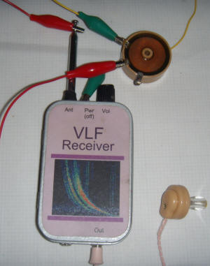
To give you an idea just how big this signal is, take a look at the signal level meter on a VLF receiver located about 100 feet from the meter:
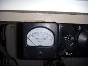
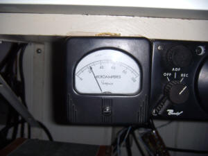
The first meter shows the low background in the brief moments when the power meter isn't transmitting. The receiver is tuned to 240 kHz and uses a small amplified loopstick antenna.
The first step that occurred to me was to bypass both of the AC lines to the good ground at the main breaker box. An electrician installed filter capacitors (5 uF, 380 VAC motor caps that exhibit a dead short to 200 kHz with reasonable length leads) behind two dedicated breakers.
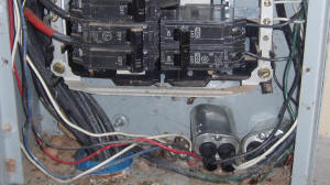
The two capacitors are just laying at the bottom of the box and are connected to the two 120 volt legs through the two breakers at the bottom right. The other leads of the capacitors are connected to the neutral buss bar which is bonded to the earth ground that runs straight down into the ground below the box. The capacitors succeeded in lowering the voltage on the two hot lines but the current flowing in the ground turned out to be the bigger problem. My home has metal plumbing and a variety of appliances and old-fashioned wiring techniques connect the plumbing to the electrical ground in the house. Any electrical noise current flowing from the power lines to ground will also flow into the home via the ground wires and find an alternate path to ground. This current flow generates magnetic fields around the conductors, both wires and pipes. It also produces a potential difference between electrical ground and an antenna earth ground which will appear as a signal in a grounded receiver.
Ground loops occur when there is an alternative path to ground for noise signals on the electric wires. A typical alternative path would be a clothes washing machine with a little copper ground wire hooked to a cold water pipe. The washer chassis is connected to the electrical system ground via the line cord so the little wire ties the electrical system's ground to the water system. Current can flow through the electrical system, through the washer, and into the cold water pipe (assuming the plumbing is metal). This turns the water pipe and house wiring into magnetic field generators, spreading the noise throughout the house.
It can be hard to think of all the potential grounds and a simple system can be thrown together to trace the currents. First, plug an audio signal generator into an outlet near the breakers and connect the center pin of the generator's output to a cold water pipe through a 10 ohm resistor and the ground to the breaker box ground. If your audio generator's ground terminal is grounded via the line cord, you can skip the breaker box connection but choose an outlet fairly close to the box. Audio current will now be flowing through the water pipe to any electrical ground connections and then back to the signal generator. Connect an open, solenoid style coil of a few millihenrys to an audio amplifier:
I've connected a 50 millihenry air-core coil to my pocket VLF receiver which is essentially an audio amplifier. When the coil is held with the flat faces perpendicular to the pipe or wire in question, the magnetic pickup is maximized. Holding the coil with the body 'lined up' with the pipe or wire in this manner will give loud reception of the generator's output if current is flowing in that path. If your pipes and wires are exposed, it becomes a simple matter to follow the signal. But, even if your pipes are buried, you might be able to follow the signal and you can certainly test pipes under sinks, line cords and even metal structural components. Turn off whatever you can in the house to keep the hum down to a bearable limit.
The solutions aren't always ideal but here's what I discovered and what I did to break my unwanted current paths:
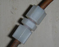
My icemaker and dishwasher were both grounded to the electrical system and to the water system. I simply cut the copper pipes under the sink and added nylon pipe couplers, breaking the continuity of the pipes:
My satellite antenna was grounded to a water pipe outside and the receiver to the electrical system. I simply removed the water pipe connection. Only a direct lightning strike could overwhelm the ground but I might add a spark gap arrestor where I cut the ground wire.
My washer had a ground wire connected to the cold water pipe so I moved that connection over to the electrical outlet box (really a redundant connection since the line cord does the same thing).
My TV distribution amp had a wire over to a water pipe. It seemed to have audio current in it but it uses a molded power supply. I discovered the signal continued along one of the coax cables to a tangle of TV, TiVo, VCR and other equipment. I simply removed the TV amp since the switch to digital TV has rendered the antenna connection obsolete.
My general-purpose whip antenna has its coax conveniently grounded to a cold water pipe right by the base. I'm going to live with that one! (Note: adding the isolation transformer mentioned below breaks this ground loop.)
One last strange one: one water pipe passes through a
concrete ceiling in the basement (old house - they don't make them like this
any more) and rubbed against the metal screen:
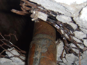
That screen also made contact with some recessed lighting cans that may also
be grounded to the electrical system. Bending the screen back stopped the
current in the pipe but I didn't pursue trying to isolate the electrical
system from the screen. Probably should...
There is noise current flowing in the line that goes to the microwave but I don't know why. There is a metal vent that penetrates the roof and it might be contacting something somewhere along the way. I'll insulate that vent pipe from the microwave some day.
The little current tracer works like a charm and can even detect current flowing in large-diameter toilet pipes. (The old cast-iron types in my old house.) The complicated paths the currents take is fascinating.
Other ground paths you may have could include a hot tub, electric water heater, demand water heater, swimming pool, automatic sprinkler system, water chiller, or any appliance that mixes electrical with water or gas pipes. Also watch out for unintentional couplings like water pipes that are touching electrical conduit. As I re-read my own list, it occurs to me that my stove uses an electric starter and is connected to the gas.
Once you've vanquished the noisy ground currents, add an isolation transformer between the antenna and the receiver.
For LF, it is hard to beat one of those little network transformers like the PE-64934. Hook one side to the antenna and a good ground near the antenna and the other side to the receiver. Try swapping the connections on one side to see which phasing is better; it does make a difference. A voltage follower of some sort may be added between the antenna and transformer to prevent the transformer from loading the antenna too much. An ordinary gate-follower or emitter follower should suffice and running such a buffer on a molded supply with no power system ground seems to preserve the isolation. If you receiver is sufficiently low noise, the loading won't hurt the signal to noise ratio. A TL592 differential amplifier (or something similar) connected to one of these isolation transformers would make a great LF preamplifier. One input of the '592 would connect to the antenna and the other would connect to the antenna's local ground. Suitable surge suppression should be added. The outputs would drive the isolation transformer. The common-mode rejection of the '592 combined with the transformer isolation should keep line-related signals out completely. Or, the TL592 could be connected after the transformer to boost the signal if it is too small for a less sensitive receiver like some selective level meters. The preceding assumes the antenna is electrically short and is basically acting as a voltage pickup.
For VLF listening, a lower frequency transformer is required. An ordinary audio transformer with high-Z windings is a good starting point. Also check the junk box for one of those old microphone transformers with the internal electrostatic shield. There are also video isolation transformers available that work well and have surprising bandwidth. (Some of these video transformers might not perform as well as the little network transformer at LF and above.) A differential amplifier made from two or three op-amps would make a great preamplifier to drive the isolation transformer for VLF. To test the system, connect the inputs of the amplifier together and touch them to the antenna ground. I simply slip a 50 ohm terminator on the coax to the amp input and rest the connector on the antenna jack so that the center conductor isn't making contact. The common-mode rejection of the amplifier should give very little output. I have found that such a setup allows me to have a good water pipe ground right at the base of the antenna without hum issues.
For ELF, ask me about some very special James transformers I have. They are simply amazing with double electrostatic box shields and 4000 Hy inductance. That's still 180,000 ohms at 7 Hz! They could simply be connected between the antenna and amplifier for frequencies above a couple of hundred Hz. But for ELF they should be driven by a high-Z preamplifier. They tend to 'poop out' above about 10,000 Hz. But then, so do my ears.
I'm confident enough to declare victory at this point. The addition of the isolation transformer has not only removed the last vestige of the power meter noise but it also eliminated the last bit of buzzing hum that I had always assumed was coming in via the air. There is still some noise current flowing in my water pipes but I switched the antenna ground to an unused iron drain pipe (for an old washer hookup). That pipe is buried deep and runs for 30 feet or more and there is no source of noisy ground current. Modern homes probably don't have such options and a good outdoor ground system is probably needed. For very low frequency work at LF and below, the ground wire doesn't seem critical. I used a long piece of hookup wire to try various grounds around the house with good results and switching to a heavy, short wire didn't make a difference. There isn't much current flowing in the wire and it's a dead short when compared to the electrically short antenna.
Some time ago, I tried to see Schumann Resonance with the whip on my roof. There was so much line interference it was comical. Now I think I can see the peaks:
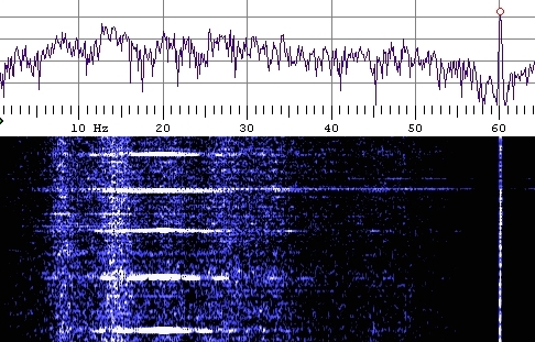
I don't know what else would cause these obvious peaks in the noise. The repetitive white lines are due to a large motor, possibly the neighborhood sewer pump.