
These circuits generate high voltages and can cause dangerous shocks! Do not build these devices unless you are experienced and qualified to work on high voltage devices.
|
World's Smallest Geiger Counter (not really a Geiger counter) |
![]()
The difference is subtle; the feedback signal increases the voltage on the base of the 2N4403 to stop the oscillator instead of stealing current from the capacitor on the emitter. The result is much lower power dissipation when there is little or no load on the high voltage. The new circuit draws less than 1/2 mA when operating at 9 volts without a load using a 1:1 600 ohm audio isolation transformer. The 3 volt circuit may be modified in the same way but make sure to switch to a MPSA18 (or a similar very high gain transistor). The 120 volt zeners are also an improvement over trying to grade ordinary diodes; grading is just too much trouble! A 1N5273A is a typical type to try. Remember, this circuit can only supply a few microamperes so an ordinary 10 megohm voltmeter will load the output too much. (500 volts/10 megohms = 50 uA.)
The transformer in the prototype is a small isolation transformer with opposite ends of the primary and secondary connected together to boost the output voltage. Other transformers will also work, including tiny audio interstage transformers, as long as the impedance is relatively high on both windings. If you don't get a high voltage, try reversing one of the winding connections. If the current doesn't cut back with no load, try the techniques mentioned in the note above. The circuit will work without the secondary connection simply by connecting the collector of the MPSA42 directly to the first .02 uF cap. and diode and leaving the secondary winding disconnected. Using the two winding voltage boost is recommended when attempting to run the circuit on a lower supply voltage.
Here is my favorite 9 volt version using only a molded choke (the ones I have in quantity):
Other combinations of zener diodes and gas tubes may be used to get the desired output voltage but the upper limit is about 1000 volts.
The 0.1uF capacitor on the base of the MPSA18 will reduce the current consumption when using Lumex or some other types of gas tubes and some zeners. It is unnecessary in most cases but the right value or no cap at all can push the no-load current really low, depending on the characteristics of the selected breakdown devices. This circuit will operate on lower supply voltages but, at some point, it will not "cut back" and will draw several mA all the time. The transformer version can more easily generate higher voltages when operating from lower battery voltage. Keep in mind that the current consumption of this circuit is very low when operating properly and a 9 volt rectangular battery will last a long time, giving perhaps a month of continuous duty.
The output voltage can vary by up to 20 volts from no load to a light load due to the measurement of the voltage before the voltage doubler. The regulation is much better once a little current is flowing. For much more precise regulation, connect the zeners or gas tubes and resistor from the base of the MPSA18 directly to the output. You will need twice the breakdown voltage, however. I connected four neon lamps, type WL-1MH (similar to NE-38), in series with the 10 megohm from output to base and the resulting voltage was 540 volts and only changed 7 volts when loaded by 300 meghoms. Switching over to 4, 120 volt zeners gave an output voltage of 520 volts that changed less than a volt when loaded! The current drain seemed to improve in both cases, dropping to 200 uA with no load. If you don't mind using twice the number of zeners, this is a nice modification. For fun, I replaced one of the high voltage zeners with several lower voltage zeners until I hit exactly 500 volts. It took 6 zeners to do the job and I suspect it's overkill for most projects. But if you want a precise voltage and have a sufficient pile of parts, why not!
![]()
Below is the older design but it works fine, too. It draws a little more current when unloaded, typically 1 mA. A choke should work in place of the transformer, too, with similar limitations. Ground unused gate inputs. The '4093 may be a '4069 hex inverter.
Here is a 700 volt or less power supply for powering a small Geiger tube or other very low current device. The circuit is very efficient when no current is being consumed which is typically the case in a Geiger counter. Geiger tubes draw about 100 uA when they pulse but the pulses are very short and relatively far apart (hopefully). The current drain from the 9 volt battery is less than 1 mA with no load. The circuit will supply a bit more current when operated from 12 volts. The output voltage is set by the string of devices that includes the neon bulbs. Select a combination of neon lamps, varistors, zeners, etc to achieve the desired voltage. Good results may be had by selecting one or two ordinary small-signal silicon diodes with the desired breakdown voltage. The current in the diode will be quite low and no damage will result.
The circuit shows the power supply in a typical Geiger counter circuit but it may be desirable to use a larger resistor from the high voltage to the tube - see the manufacturer's recommendations. A 10 megohm is a safe value for most tubes.
Note: This generator cannot supply much current. An ordinary 10 megohm voltmeter will pull the output voltage quite low; a very high impedance voltmeter is needed to directly measure the output voltage. A 1000 megohm resistor in series with a 10 megohm voltmeter will give a 100 to 1 voltage reduction and will not overload the circuit. Large Geiger tubes may also draw too much current in moderate x-ray fields so a more robust generator may be needed. (See the 3V version below.)
The other two gates in the '4093 may be used to construct a beeper that will drive an ordinary piezo speaker:
The 1N914 (or any similar diode) connects to the output of the last gate above. When a pulse triggers the first gates, the diode becomes reverse biased and the oscillator is allowed to operate for a split second. A '4069 hex inverter will also work but ground the unused inputs.
![]()
Here is another version that will supply more current for a larger Geiger tube and runs on two cells (3 volts).
![]()
The above circuit was used to construct a home-made Geiger counter employing a 10 inch Geiger tube (LND 78014). The pulses from the tube were converted into 3 volt, fixed-width ( a few hundred microseconds) pulses suitable for averaging using the following circuit (updated 5/5/04):
The pulses may be counted with a digital circuit or may simply be averaged to apply to an analog meter:
The indicated switch is a two-pole, six-position switch. The resistor values in the meter circuit were selected to give the proper reading on one of the two pre-existing meter scales which differ by a factor of two. The older meter required 60 uA to reach full scale even though it was originally a 50 uA movement. In the actual prototype, an additional position and pole were included. The third pole switches in a 1 meg to ground at the input of the op-amp to reduce the signal by two for one more range. the same 19.6k resistor is used for both positions. In a new design, the op-amp and meter circuit would be modified for the chosen meter and desired scales. The op-amp must be one that operates on 3 volts or less and must have a very high input impedance.
![]()
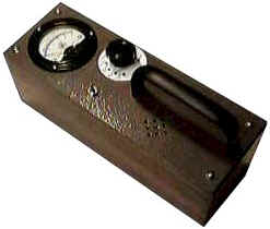
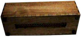
The Geiger counter prototype was built into a homemade wooden box:
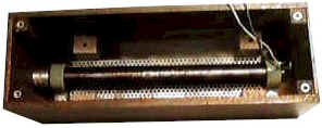
The tube is mounted with cable clamps over a hole in the bottom of the box covered by a perforated aluminum shield. The holes in the perforated aluminum directly below the tube were drilled to a larger diameter to block less radiation.
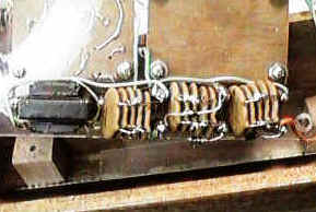
The voltage multiplier is mounted on the underside of a Plexiglas subchassis:
The other circuitry is mounted on two pieces of laminate on the top side of the subchassis:
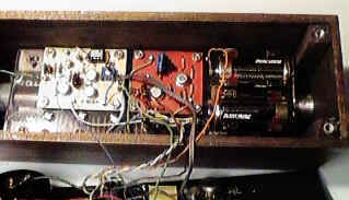
The front panel holds the meter, switches, resistors, speaker and 4.7uF capacitor.
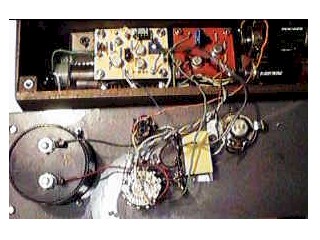
The wiring gets a little messy when the end of the project is in sight! It was discovered that the connection from the capacitor to the op-amp must be well insulated. Bend the op-amp positive input lead up into the air and directly solder the wire. Add an additional low leakage small value film capacitor (0.1 uF is fine) to ground at the op amp plus input since the 4.7uF is some distance away.
The front panel is also made from lexan painted on the outside with metallic hammertone paint.
The performance of this detector is quite good. The background radiation near 0.016 mR/hour give a 2/3 full-scale reading making slight changes in the background easy to see. The extra-long averaging time (44 megohm) gives a very steady reading, albeit slow to respond. This is a sensitive counter and is easily "pegged" with an ordinary test radiation source or even a Coleman lantern mantle.
![]()
Techlib reader Dave Mouat modified the circuit as shown below:
In the diagram I've put the transistor numbers as the ones I've
used, although you can use standard 2n3904's etc in these positions without
problems as they're similar spec. The transformer used is a normal audio output
transformer, such as an LT700, and the transistor driving it in this case is a
Darlington pair device, number BD675 (not sure of any equivalents here, but I
imagine its not critical)
The BAT43 diode is just a Scohttky device, and was used simply because of the
low forward bias voltage drop. You'll notice another diode and transistor across
the main drive transistor, this simply derives a voltage high enough to fire the
clicker and LED, in practice its about 12-16volts, quite a useful value if we
decide to run anything else from this supply at a later date. The clicker (drawn
as a speaker) is one of those low impedance devices you see in cordless phones
or kids toys for a ringer, works very well in this position, a nice loud click.
The shutdown transistor (connected to the string of zeners) I've
found needs to be something with a reasonable gain, although the one I used
seems to work fine, regulation would probably be better with one of the MPSA
devices you've used and a higher value load resistor. This is a great way to
reduce power consumption, as in this situation the circuit is firing when
(output voltage/2) falls below the threshold, a better way would be to try and
measure the main output voltage directly, although I've had no luck with this
method. The capacitor which drives the base of the main drive transistor (BD675)
is quite critical, it will work down to 1uF, but don't go above 3.3uF, as the
power consumption went through the roof when I tried this, the LT700 was
obviously becoming saturated.
The badly drawn GM tube that I used was a SBM21, a tiny little tube only 21mm
long (can be seen in the top left of the photograph of the unit), i got mine
from a Russian guy on eBay, unfortunately they're not very sensitive at all,
background counts on this tube are about 4-8 clicks per minute, whereas my
CD-V700 and DRSB-01 both disagree and give something closer to 2-4 times that
value. Still not bad for such a tiny counter.
At one point I tried a small transformer from one of those cheap disposable camera's, this worked and gave reasonable efficiency but whined like crazy, i prefer the off-the-shelf LT700 audio transformer. Also, because I built mine on Vero-board i found that I had to put a 470k-ohm resistor from the base of the first detector transistor down to ground, as the board was conducting and turning it on. I expect there are probably many modifications that could improve the circuit, so you can post it on the site if you like and maybe it will help someone else.
![]()
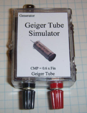
This little gadget will simulate a 500 volt or less Geiger tube when driven by a signal generator of sufficient amplitude, typically 5 volts p-p or greater. The purpose is to generate a steady, precise number of counts per minute so that the Geiger counter's meter may be calibrated.
The circuit rectifies the signal generator's output to provide power for the circuit so no battery or power supply is needed. The generator's frequency is divided by 100 so that low counts per minute may be simulated with ordinary bench generators that typically only go down to 10 Hz (600 CPM).
The two input diodes may be just about any schottky type or even older germanium diodes. The generator should be able to supply over 5 volts peak-to-peak. Higher amplitude is fine and will stretch the pulse width slightly. I vary the amplitude to modulate the pulse width when experimenting. The pulse width is also set by the 2.2 nF; increasing the value will increase the pulse width. The width is about 200 uS with the values shown in a typical Geiger counter circuit operating at 400 volts. The 2N3440 was chosen for high breakdown voltage with a 22k resistor connected from base to emitter. The prototype's transistor breaks down at about 600 volts, making this device useful for simulating tubes operating at up to 500 volts. The breakdown voltage was tested at a low current. Since the divider is wired to divide by 100, the counts per minute is equal to the frequency of the generator multiplied by 0.6. Setting the generator to 100 Hz will give 60 counts per minute. To simulate a higher voltage tube, a higher breakdown transistor will be necessary. Make sure to test the transistor's breakdown voltage with the 22k from base to emitter. The breakdown will be higher than with the base open but lower than with the base connected to the emitter directly.
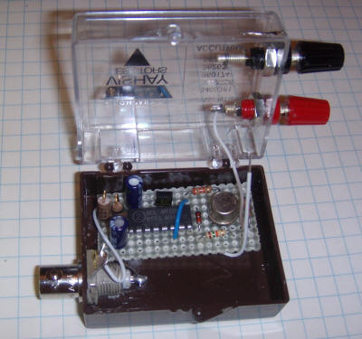
Construction technique isn't critical. The prototype is built into a plastic box with a BNC for the signal generator connection and miniature binding posts for the simulated Geiger tube output. Please don't notice the typo on the label! ('CMP' instead of 'CPM') Note that this circuit is for Geiger counters that ground one end of the Geiger tube (most do). It might work with other types if the Geiger counter case is floating relative to ground.
![]()
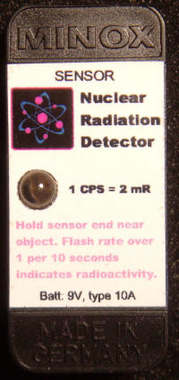
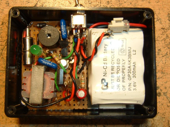
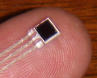
It probably isn't the smallest and it isn't really a Geiger counter (no Geiger tube and it doesn't count) but this really small radiation detector flashes the LED every time a particle of sufficient energy strikes the tiny PIN photodiode. The small detector gives about 1 pulse per second with a 2 mR source (using an old fallout shelter Geiger counter and test source as the reference). This sensitivity is enough to determine if a lantern mantle is radioactive or a mineral sample is uranium. Most importantly, its small size makes it inconspicuous! A typical thorium lantern mantle gives about one flash every two seconds. Thoriated welding rods give a blink about every 10 seconds and weak Vaseline glass marble gives only one count every 45 seconds so the detector becomes impractical for the weaker sources. A larger PIN diode is the simplest way to improve the sensitivity.
The circuit is designed to consume virtually no power so that the detector can operate for long periods without a power switch. The total current drain when the LED is not flashing is only 3 uA, giving an operating battery lifetime for the wimpy type 10A (30mA-Hour) of over a year. The random flashing of the LED due to background radiation might shorten that lifetime. A regular 9 volt rectangular battery would be hardly affected.
When particles hit the PIN diode, tiny positive pulses appear on the gate of the 2N4417. These pulses are amplified by the 2N4117 and the MPSA18 and applied to a two-transistor monostable lamp flasher. The 2N4117 is biased by selection of the 1 megohm resistor in the source such that the drain is at least a couple of volts above the source. The drain is DC-coupled to the MPSA18 and it should have a couple of volts from collector to emitter, too. The actual values aren't particularly critical as long as there is a little voltage across the first two transistors; the pulses are pretty small. The 2N4401 is biased by two, 62 megohm resistors connected in series and a 3 meghom to ground so that the flasher circuit is on the verge of flashing. If the 3 megohm is too large, the LED will flash constantly and if the 3 megohm is too small, the circuit will not be sensitive. Other high value resistors may be used but the values should be well above 1 megohm and the ratio should be chosen such that the flasher is easily triggered by the amplified pulses. The flasher doesn't draw significant current when it isn't lighting the LED so the quiescent current is due to the first two amplifier stages and is only about 3 uA.
This "Geiger" counter flashes the LED just like a Geiger tube detector and a crystal earphone connected across the LED and resistor will give clicks just like a Geiger counter but the detection mechanism is significantly different. The main difference of interest is that the PIN diode usually converts the entire particle's energy into a pulse so the pulse height may be used to determine the original energy in the particle. (I should mention that high-energy Gamma rays will plow right through the PIN diode without losing all their energy. The pulse will be big but not necessarily representative of the real energy. Gamma ray detectors often employ large blocks of material to capture the whole particle.) Sophisticated detectors sort the pulses by amplitude and can determine what element produced them but this simple detector simply looks for pulses above a certain level.
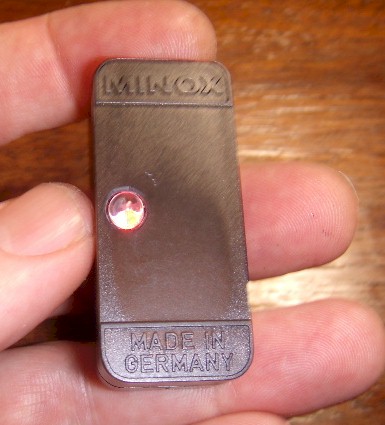
Certain precautions must be observed to make a working unit. First of all, the PIN diode is extremely sensitive to light and it must be kept in total darkness. I even had a problem with light coming in through the body of the LED even though it was mounted in a separate compartment! I eventually painted the back of the PIN diode with black "liquid tape" and added an internal light shield. The circuitry is also ridiculously sensitive to electric fields and the circuitry must be shielded. I decided that an old Minox spy camera film box was the container to use for a variety of reasons having nothing to do with good engineering! It is light tight but it provides no electrical shielding. The first step was to glue the PIN diode to one end of the case and to add internal shielding in the form of thin copper circuit board material. Solderable metal foil would also work.
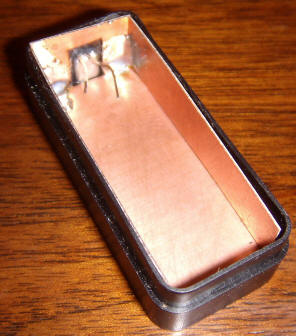
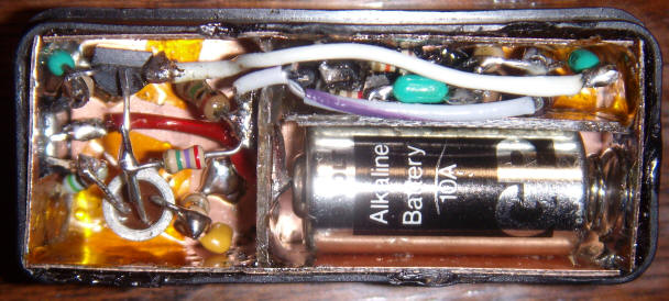
The construction technique could be called the "ship in a bottle" method. No kidding; the construction of this gadget required a lot of dexterity! The battery holder was constructed first, using part of a spring from an AA cell battery holder and a piece of PCB material for the other end. The PCB material forms the positive connection and was made by etching a pad in the middle of the board with an abrasive cut-off wheel and drilling a hole in the middle of the isolated land for the red wire. The solder holding the red wire forms the positive terminal for the battery. Once the battery cavity was made, it appeared that the flasher portion of the circuit might fit in the small cavity directly above. And it did, just barely. This location seemed good since light can come in via the LED body. The PIN photodiode is to the left in the photo above and the FET and MPSA18 are in the same cavity. Not shown is the black "liquid tape" that I dripped on the photo diode and the two wires coming through from the flasher section to block more light. Also, an electric shield was added to completely shield the electronics by adding a metal plate above the electronics with a wire connecting it to ground. This shield is held in place when the lid is installed. The amplifier is so sensitive that the tiny exposed part of the PIN diode picks up electric fields. The unit will not operate properly near large electric fields from TVs, computers, etc.
The circuit illustrates how one can use a PIN diode to get Geiger counter like pulses and a more practical package arrangement will make construction easier. I plan to take this covert detector to Wall-Mart and other stores in search of radioactive lantern mantles, minerals, etc.
![]()