
Warning: New computers may have a feature called "enable audio enhancements" for the audio inputs. Find it and unselect it! It will digitally roll off the response at the lower frequencies! Mine selected itself after an update. I replaced a perfectly good outdoor microphone before I discovered the real problem. Why are they called "features?"
Infrasound is simply sound below the human's hearing range, typically below 20 Hz. At such low frequency a true sound wave causes the local pressure to go up and down and is distinguished from air movement. In fact, breezes are the main enemy of infrasound detection and pressure changes due to local moving air can be indistinguishable from true sound waves with a single microphone, especially at the very low frequencies, say below 1 Hz. Differentiating between local effects and real sound waves that have traveled hundreds or even thousands of miles is done by correlating the output of an array of microphones with significant spacing between them; quite a project! For the amateur scientist or hobbyist the detection of local pressure changes due to air movement is probably unavoidable and can be a plus, primarily for detecting large moving objects like trucks on the nearby expressway or aircraft overhead. Alas, wind itself can do the same thing so such observation is best done on a still day.
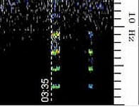
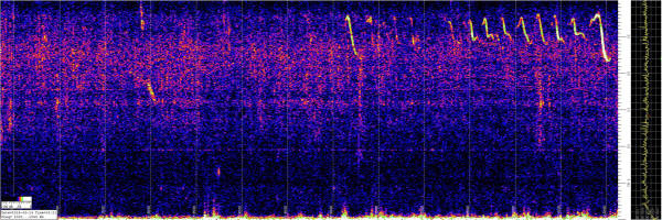
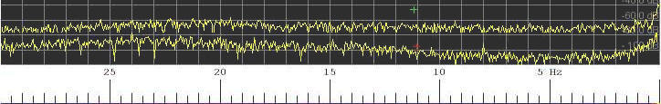
So, the projects below are for detecting "infrasonic frequencies" and not just "infrasound." Actually, they extend the range of sensitivity into the hearing range perhaps as high as 200 Hz where all sorts of interesting activity occurs, especially involving aircraft, construction machinery, and often mysterious sources. One of my early "captures" of a helicopter circling some sort of crime scene off to the east was quite impressive, at least to me:
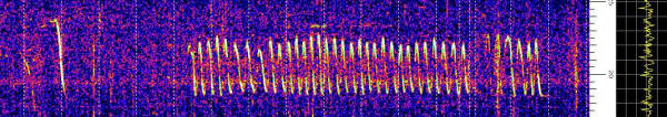
The frequency varies from 18.5 to 22.5 Hz due to doppler shift as the helicopter circles. The clearer portion lasts for about 45 minutes and I couldn't hear a thing outside.
The speed of a passing sound source can be calculated from the ratio of the lowest frequency and highest frequency:
R = Fl/Fh
V = 769 mph x (1-R)/(1+R)
(Substitute a different speed of sound for other unit systems.)
So, if that helicopter above were simply passing, the ratio of the frequency would be 18.5/22.5 = 0.822 and its speed is 769 x (1 - 0.822)/(1+ 0.822) = 75 mph. Seems plausible. Sometimes it's hard to tell the highest and lowest frequencies but keep in mind that the doppler flattens pretty quickly at the extremes. An orbiting helicopter is a bit more complicated since it's constantly turning. I'm not willing to work that out! On another plot an airplane passing in a straight line exhibited Fl of 50 Hz and Fh of 80 Hz. I calculate that it was moving 177 mph. That's pretty quick but it is often hard to tell the ultimate frequency limits; I can look at the same plot and come up with 140 mph, too. What's interesting is that the time between the two frequency extremes was about 3 minutes. It's easy to calculate the plane travelled 9 miles in that time. You can estimate the distance by multiplying that distance by a correction factor derived from trigonometry. But lately I've concluded a good correction factor is simply 1. In other words the helicopter is about as far away as the distance it travelled making most of the doppler curve; just don't include a lot of the straight "tails." It's all very approximate! Now if one could identify a helicopter using Flightradar24.com or a similar site, one could come up with a much better correction factor.
For more information regarding infrasound monitoring read about the NASA Langley Researchers' invention. If that link dies, check out the Wikipedia article on infrasound.
It's quite easy to dip one's toe into this hobby. The ubiquitous electret microphone typically has a flat frequency response to below 10 hertz with usable sensitivity to just a couple of hertz. That's also true of the typical sound card; I've read they typically start rolling off below 10 hertz. This is barely "infrasound" but it is pretty interesting, nonetheless.
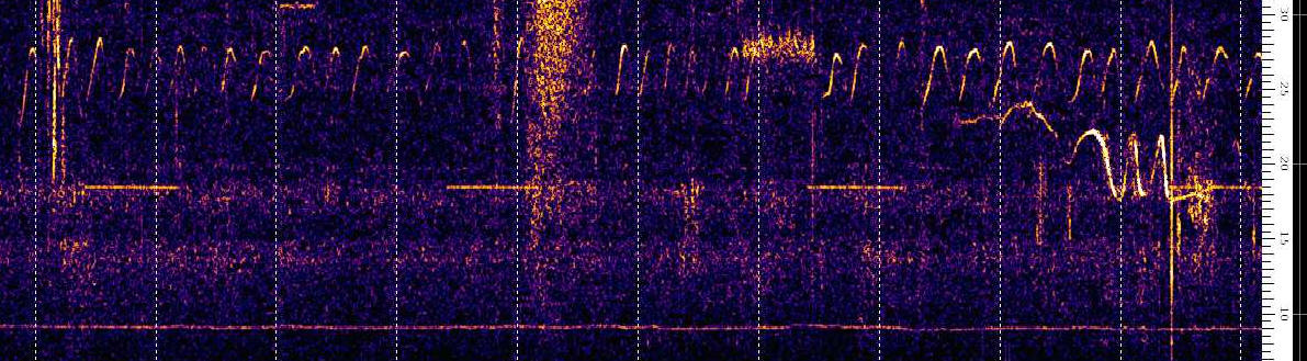
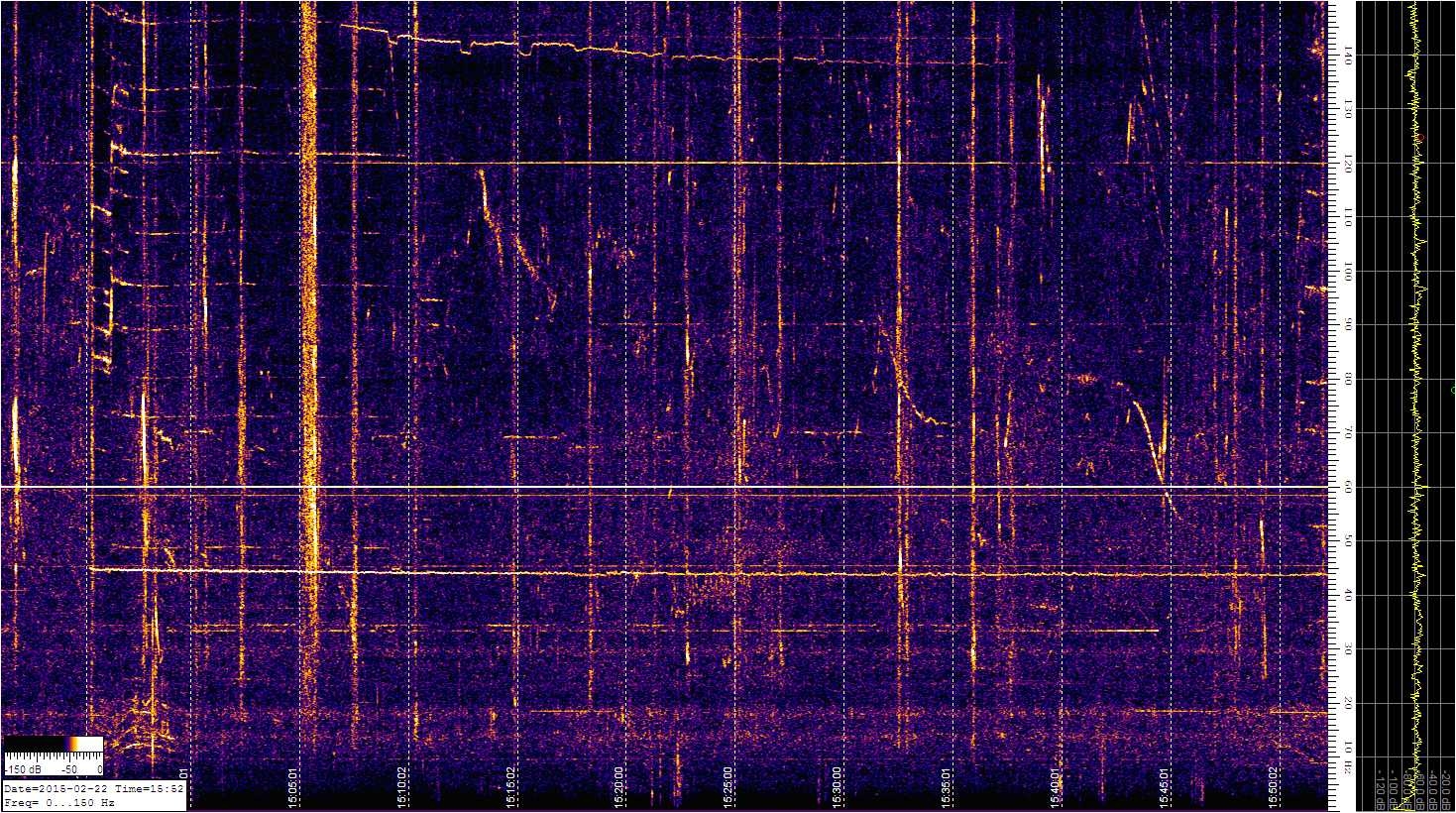
For example, here's a large image from this morning using this microphone. Note the engine starting around 44 Hz with harmonics (and possibly subs, too). That was completely inaudible outside. There's a couple of passing aircraft and a weird trace up near the top. The bright vertical line is typical of a passing jet. The low frequency humps to the bottom left are a mystery. Note that even though the sensitivity is rolled off, signals can be seen down to a couple of Hz in places. Ignore the 60 Hz line but right below it is another frequency produced by the mystery engine. No helicopters yet; they have the same backwards integral sign look but centered more near 20 Hz.
The microphone needs to be protected from the weather and air currents have to be blocked with an effective windscreen. Both are accomplished with a short length of closed-cell water pipe insulation found at any hardware store. Here are the simple steps to have a working infrasound station:
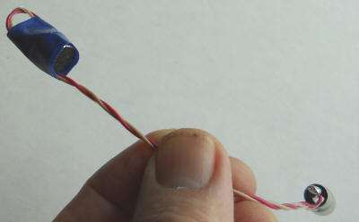
Prepare the microphone as shown in the photo, folded back on its wires and terminated with an RCA phono connector. It's folded back like that to prevent the opening of the microphone from inadvertently being pressed directly against the foam and the RCA connector was chosen because long cables with such connectors are commonplace - feel free to use something else.
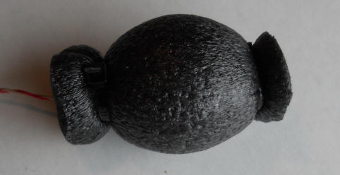
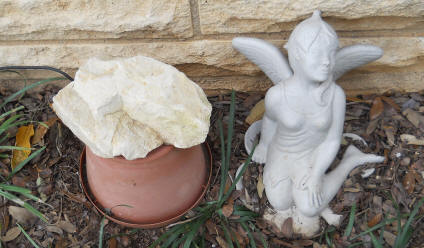
Glue the slit in a 4" length of pipe insulation closed with contact cement (or buy a length of the non-slit type) and seal the microphone and connector inside using two large cable ties. Make sure to pull the cable ties very tight to seal the ends. At first I used some silicone caulk to help seal the ends but I don't think that's necessary and it's a bit messy. Sticking this thing under a small plastic flower pot with a brick on top will do the trick! Originally I stuck the above assembly in a drink cozy sealed with a disk of foam rubber for added wind protection. But that unnecessarily attenuates the audio frequencies without much benefit. Also, place the rock such that sound can get into the holes in the bottom of the plastic pot. It turns out that the spectrum up to a couple of hundred hertz is pretty interesting.
 U
U
Use an adapter to convert the RCA phono connector to a stereo phono plug for the microphone input to your sound card. Remember that the tip and first ring of the stereo plug need to be tied together in order for the microphone to get power. Oddly, the microphone will work somewhat without power but the sensitivity will be abysmal. (Next time I build one I'll just solder the mic. to the end of an audio cable and solder a stereo earphone plug to the other, shorting the first ring to the tip. Perhaps I'll just cut the RCA connectors off of an old speaker cable.)
Download a copy of the free and truly amazing Spectrum Lab. There's great guidance on the Spectrum Lab website for setting it up. Lately, I've discovered that the program seems to set itself up properly without any "intervention." You can start by adding my settings to the configuration folder. Spectrum Lab is a little intimidating at first but it's well worth the learning curve. You can often find a "microphone boost" in the sound card control panel if you need more sensitivity.
Below is an image from last night (3/6/2015) using the above microphone. Note the two circling helicopters. One was circling for quite a while (5 minutes between dotted lines.) But also notice the 18.5 Hz on/off signal, on about five minutes every 15 minutes. And a 9 Hz signal made an appearance. What the heck is going on out there!
The other day I saw several of the "Morse code" dashed lines so I decided to track them down. They're HVAC units around the neighborhood. It's been cold so I assume the sound is coming out the gas flue. When mine comes on the signal is quite strong.
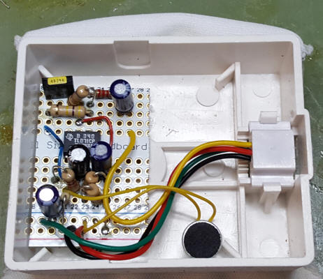
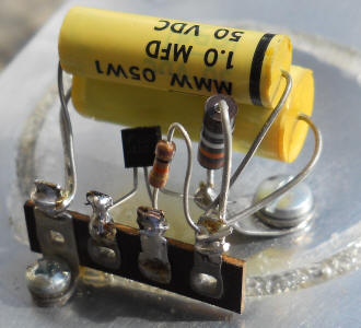
The older computer I'm using for the above microphone doesn't have quite enough gain so I built a simple preamplifier that steals power from a USB port and gives gain down to 1 Hz. It's built into an Altoids Mini tin:
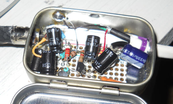
The RCA input connector is on the left and the cables to the right include 5 volts from an old USB cable and a monaural audio cable with a phono plug for the microphone input.
Power comes from a salvaged USB cable. The outer two pins on the USB connector are +5 volts and ground; use an ohmmeter to identify the wires going to the outer two pins and then use a voltmeter to determine which one is +5 volts. One of my laptops has excessive low-frequency noise on the USB power so you might want to use an old linear power adapter instead. I found an unregulated "3.7 volt" transformer-type molded supply that output about 7 volts unloaded and I added a 3-terminal 5 volt regulator.
Just about any small-signal NPN transistors will work. This preamplifier provides about 20 dB gain (x 10) and "bass boost" below 10 Hz down to 1 Hz. I used back-to-back capacitors on the output to avoid polarity problems. Just connect either both positive or both negative leads of the capacitors together. Those could be larger values, perhaps 220 uF, to avoid low-frequency roll-off if the sound card has a lower than average input impedance or if the tip and ring are connected for some reason.
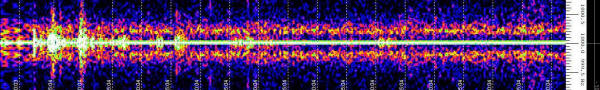
Hurricane Harvey generated quite a lot of infrasound that this mic. and amplifier detected well. Here's a snap showing the good response to below 1 Hz (8/26/2017).

Here's another microphone amplifier that boosts the gain at the low end, giving flat response to 1 Hz even when the sound card is rolling off by then. Examine the noise below 20 Hz using Spectrum Lab and determine the frequency where the gain just starts rolling off. Calculate C (0.1 uF in schematic) by dividing 2 uF by that frequency. The cap can be the nearest standard value. My plot showed a drop-off at 20 Hz and C calculates to 2 uF / 20 = 0.1 uF. With this capacitor in place the response looks "alive" down to 1 Hz. Overall gain may be increased by reducing the value of the 22k to as low as 4.7k. I call this preamplifier "better" because it has good rejection of power supply noise; USB power can be noisy.
(My setup uses both red and black phone wires for +15 due to an earlier project.) I used a TL071 op-amp but many types will work fine; it's not a demanding application. Here's the LTSpice file. Change the op-amp to something like the RH27C (near the end of the list) if you don't have the LM7301 model. Just delete the LM7301 and replace it with one in your list that's fairly "ordinary."
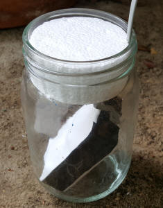
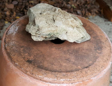
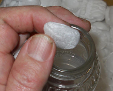
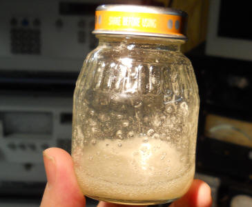
I mounted the amp and microphone in a wall phone jack, wrapped it in fine cloth (clean room wipe) secured with electrical tape. The cloth is just to keep out curious insects - probably not necessary. I inserted the assembly in a glass jar, plugged it with styrofoam and mounted the affair outside under a clay flower pot with a rock on top. The rock is positioned so as to not completely block the drain hole. Earlier I had it affixed to an antenna pole - bad idea! The wind noise was terrible. I've also added shipping peanuts to the jar to kill its resonance.
Forget this technique! Use the simple pipe insulation technique above. This approach lets in too much humidity and mine actually managed to fill with water! (Adam Savage's voice was in my head saying, "Well, there's your problem.") The pipe insulation approach seems fool-proof. And, frankly, skip any outdoor connectors; solder a cable long enough to make it indoors, then use connectors as desired. Use a larger diameter foam tube and include the circuit with the microphone. Next time I'll buy the foam tube with no slit and build the amplifier on a more narrow board to fit in the 1" tubing.
After experimenting for some time I'd have to say that all the interesting infrasound can be detected with the above setup and a good microphone. Frequencies below 1 Hz require significant work to detect with any sensitivity due to wind interference. Test microphones to find one that is flat to less than 20 Hz. They do exist. My best ones are from a kid's toy!
See the bottom of the Live Data page for a spectrum from this microphone.
A fun (if not exhausting) way to test your infrasound microphone is to open and close a door at about 2 Hz for several seconds. Close the door enough to force air in and out of the house. Here's the result from two doors in our solid rock house. These doors are on the opposite side of the house from the microphone and the heavy stone walls and interior doors suggest that the sound is going around the house and not through it, but who knows. I didn't last as long on the second door! The technique generates a pulse-like waveform hence the harmonics.
I'm not going to document this idea so it's for the more experienced experimenter. If you have a surplus "sub woofer" amplified speaker connect it to low-pass filtered audio from your microphone. I use a commercial filter set to 10 Hz but you could make an op-amp filter. Remove the cover so that you can touch the speaker cone and you will literally feel the infrasound, far below your hearing range. It's really surprising, like having a new sense. We had heavy construction on a highway nearby so I decided to make a video of the speaker in action. I've added a couple bells so you can see the action. Now I'm contemplating some sort of visual time-domain display, maybe a light bar.
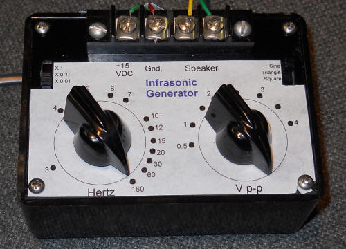
You might become interested in the lower frequencies at which time an indispensable tool becomes an infrasonic generator, especially for checking microphones and sound cards.
The following circuit uses a single CD4049UB to generate sine, square, and triangle waveforms down to very low frequencies (.03 Hz or even lower if desired). A unique wave shaping circuit give harmonics as low as -40 dBc even at 30 millihertz without long start-up wait times. I made a short video of this circuit driving a speaker at about 1 Hz and an oscilloscope at 0.1 Hz. There's a little distortion as I forgot to lower the amplitude a tad, it's just barely clipping at full level into an 8 ohm speaker.
Also see the larger .pdf of the above schematic.
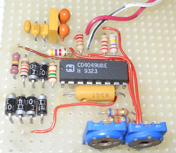
The left half of the circuit generates the triangle, square and sine waves and is pictured below before the rest of the circuit was added. I think the circuit will work with a CD4069, too. (I modified the second harmonic distortion adjustment in an attempt to accommodate both parts.) But remember that the CD4069 has a completely different pin-out.
It's amazing how good the sine wave can be with careful adjustment. I recommend adjusting the two pots while looking at an FFT spectrum analyzer (Spectrum Lab would do the trick). I'd recommend multi-turn pots if you really want the best performance. Set the frequency to about 30 Hz and adjust the pots to minimize the 60 and 90 Hz components. Careful adjustment will yield harmonics better than 40 dB below the signal for these low frequencies. Frankly, for infrasound experiments the harmonics don't matter that much but it's fun to get so much performance out of a hex inverter.
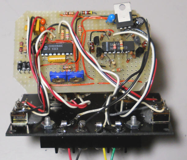
The amplifier section uses my earlier audio amplifier biasing scheme to form a bridge-type output with one side supplying the required DC offset voltage. The precision of the biasing scheme allows for DC-coupling without concern for high DC current in the speaker.
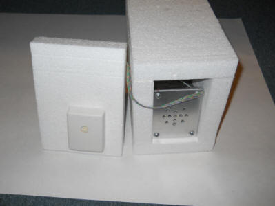
You will quickly want the ability to test various microphones as candidates for infrasound monitoring. It turns out that a tiny speaker can generate infrasonic pressure changes in an airtight container if the speaker is mounted on the container's wall, forcing air in and out. The response is quite flat from DC up to low audio frequencies allowing homemade microphones to be compared to factory-characterized electret cartridges. It's best to use low frequencies to avoid resonances inside the box, say below 100 Hz. The generator directly above will drive the speaker adequately.
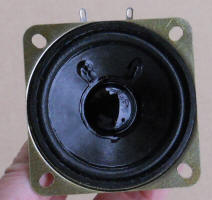
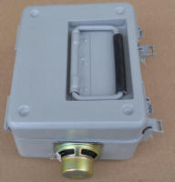
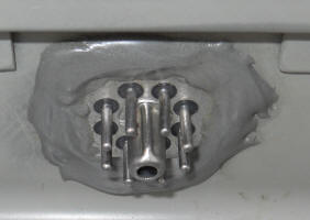
The box needs to be completely sealed, including the speaker cone itself. Some cones have intentional tiny holes to equalize pressure in the speaker's enclosure. Any such hole must be found and patched with a little silicone rubber or vinyl glue. It's also a good idea to spray the paper cone with a good acrylic coat to seal any cracks or tears. The size of the speaker isn't very important but it's best to pick one that has a lot of play in the cone. But even a "junky" speaker out of an old transistor radio will work with the ultimate pressure level being lower for a given drive power. Hopefully, a successful microphone will be plenty sensitive but it's nice to have the pressure to test the more deaf microphones. Glue the speaker over a 1" hole in the case using plenty of vinyl glue (Goop). But have several Q-tips on hand to remove any excess glue that's coming in contact with the moving part of the cone before you seat it against the case. Work quickly; the glue starts to set up right away. My test chamber below is made from a water-tight case for an old military meter. Other possible enclosures include ammo boxes, outdoor NEMA boxes with seals, watertight cases for camping and storage, and even pressure cookers.
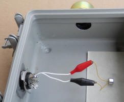
The case has an 8 pin hermetic connector that serves as the electrical feedthru, allowing me to connect microphones to a tube socket for quick connection. Such connectors can be harvested from old military-style relays, oscillators and other modules. A modern water-tight connector is another option.
If you use your scope to monitor the output of your microphone remember to use the DC setting. The offset voltage can become a problem so insert a non-polar 10 uF in series with the scope input. If the scope has a 1 megohm input impedance, the 10 uF will give a flat response down to about 16 millihertz. That's pretty low but to go lower, consider making a differential amplifier that lets you apply a balancing DC on the opposite input. Or use the infrasonic converter below and measure the results using an FFT program like Spectrum Lab.
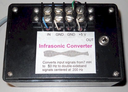
Most sound cards have a low-frequency response limit of about 10 Hz requiring additional provisions for monitoring the lower frequencies. The infrasonic converter shown below adds 200 Hz to frequencies from about 7 millihertz up to around 50 Hz. So "DC" comes out at 200 Hz and 13 Hz comes out at 213 Hz. This offset allows for the use of an ordinary sound card for monitoring infrasonic frequencies near zero hertz. This device is intended for low level signals in the 10's of millivolts as from a microphone.
Watch the polarity of the 2.2 uF capacitor on the input when using a DC-coupled electret microphone. Flip it around if the microphone voltage is higher than 2.5 volts. Or, just use a non-polar capacitor. Ignore the "LJ415" inductor and orange capacitors in the photo below; those formed a bandpass for an earlier design and are no longer in the circuit.
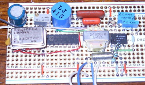
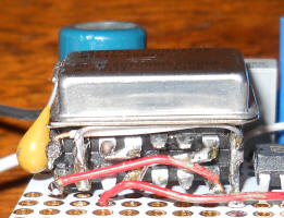
This circuit can be built in a number of ways. First, you need a square wave at 200 Hz with a 50-50 duty-cycle to drive the analog switch at pin 11. But that can be done any number of ways. I'd make it crystal-controlled so the zero doesn't drift over time. To save protoboard I had fun stacking the clock and two divider ICs:
Secondly, The two 22 meghom and two 100k resistors on the first amplifier have to be fairly precise since any DC offset will be amplified by the op-amp. Just tweak any one of the values to get near 2.5 volts at pin 7. It would be better to generate a 2.5 volt "virtual ground" and us a 10 megohm and 47k ohm for those two dividers to that voltage. (A couple of 1k resistors in series would be adequate.) Or use split supplies and tie those resistors to ground.
The audio transformer is a 6:1 transformer I have by the hundreds but practically any other type will work like the 10k : 2k interstage I specify. The transformer is nice in that it breaks the ground connection to the computer. Null the 200 Hz using an FFT analyzer but take plenty of time; the circuit has very long time-constants to accommodate infrasound.
Having all this nifty equipment led to some fruitful experiments with little electret microphone cartridges. A friend sent me a generous bag of microphones recently and my initial tests show that they have a low-frequency response roll-off near 10 Hz. I simply sprayed the back of one with clear coat and suddenly the response was flat to below 2 Hz! The spray sealed the air space behind the diaphragm, preventing the pressure from equalizing. The problem with simply doing that is that barometric pressure changes will probably press the mylar against a stop and the mic. will be rendered useless; they need to breathe a little. So, what's needed is a bigger air space for the back side of the microphone and a much slower leak.
Note: There are two factors determining the low-frequency end of a condenser microphone, the time-constant of the breather hole and air space behind the diaphragm and the time-constant of the diaphragm capacitance and the resistance of the amplifier. One is a mechanical time-constant and one is electrical. I suspect that I sealed the back of the microphone mentioned above quite well and the response is now set solely by the leakage of the JFET.
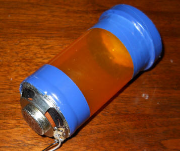
Here's a test jig for determining the electrical frequency response of electret microphone cartridges.
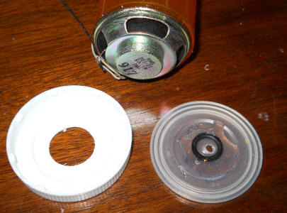
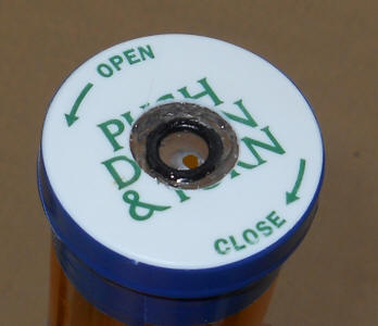
That's a pill bottle with a speaker glued to the bottom over a 1/2" hole using "Plumber's Goop." The white lid has a large hole big enough to easily pass the microphone body and the liner has a small hole just big enough to let the sound in (or out as the case may be). I've glued an O-ring selected for my mic. cartridge to the liner with more goop. The O-ring is on the side of the liner facing the lid. The idea is that I will be able to slip different microphones in and out easily. I like that the wires don't have to pass through the bottle.
It turns out to be a little difficult to get an adequate seal so take some additional steps. After the glue holding the speaker dries, run another bead around the edge. I added tape, too. Make sure to treat the cone of the speaker with a clear coat spray to make it completely airtight. Also, add a thick ring of glue between the liner and the white cap to seal them together then use more glue (and tape in my case) to seal the lid to the bottle. Lubricate the O-ring with a light film of petroleum jelly or silicone grease and refresh that now and then. With a good seal, this simple device lets you measure the bottom end of the electrical frequency response of the microphone. In essence, the little breather hole built into the microphone can't bleed the pressure out of the bottle's large air volume quickly enough to have an effect on the frequency response. It's as though the entire pill bottle's volume were behind the microphone diaphragm. With this jig I quickly determined that my bag of identical-looking microphones have electrical frequency response ranging from below 2 Hz to 20 Hz. Of course, the first one I tried was the 2 Hz unit! There would be no point in mounting one of the 20 Hz microphones in a case with a large back volume in an attempt to achieve a lower bandwidth but the 2 Hz unit would be worth the trouble as the mechanical leak designed into the microphone limits the low end to about 6 to 10 Hz.
This project is a bit insane! You might consider smaller holes, perhaps around 1". Also, I've discovered that ordinary electret microphones can be coaxed into good performance below a few Hz (see top of page) and that's plenty for most of what is interesting down there. Below 1 Hz other issues like wind become a problem and it's not all that exciting anyway.
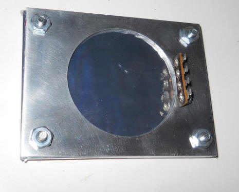
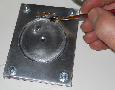
It turns out to be a fairly straightforward project to build a king-sized condenser microphone for infrasound experiments. I built the entire microphone with ordinary hand tools and I didn't encounter any significant difficulties although certain steps require special care. The main components were fashioned from three 4" x 5" x .125" aluminum plates, all done with a hand drill, bits and hole saws. I taped the three pieces together, marked the holes and used a hand drill:
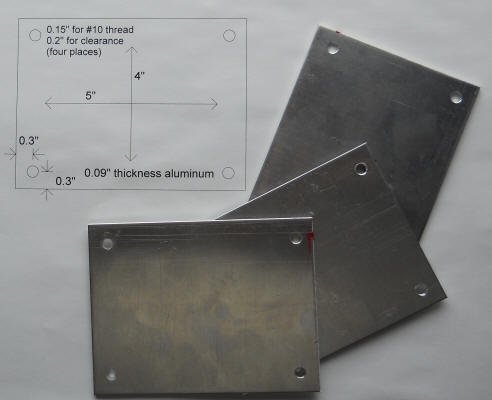
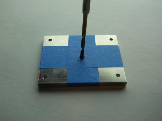
Drill all the small holes with a drill suitable for tapping for whatever size bolt you want to use to hold it all together. I used 10-24 bolts so I drilled with a #25 drill ( 0.1495"), Only the plate with the smaller large hole will be tapped, the other two plates will be drilled out to clear the 10-24 bolt.
I put a little red paint on one corner for future registration. Doing it again, I'd file a groove that can be felt through the mylar. Or, you could use a more precise method of machining! I wanted to stick to simple methods everyone could try. Once all the panels had five holes, I drilled the larger holes and a hole pattern for the sound inlet:
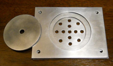
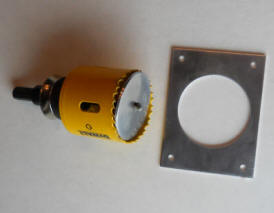
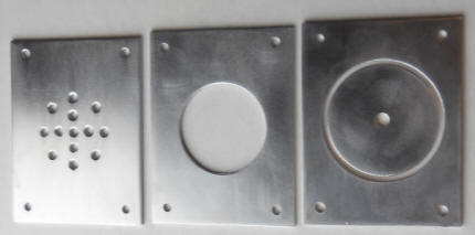
My large holes were ambitious at 1.75" and 2.25" but smaller holes will work fine, too. Save the cutout from the larger hole as it will become the pick-up plate. You do want the remaining cutout to have a somewhat larger diameter than the smaller hole so that it has a shoulder to rest on. Clean all the burrs and sand the edges smooth with sandpaper followed by steel wool. Feel free to use any hole pattern for the sound inlet. I suspect it would work fine with just the single small hole, at least for infrasound. Tap the corner holes in the plate with the smaller of the two large holes and drill out the corner holes on the other two plates to easily accommodate your chosen bolt size. I'd make those holes a bit roomy since a little slop will make assembly easier.
See the update below this paragraph.
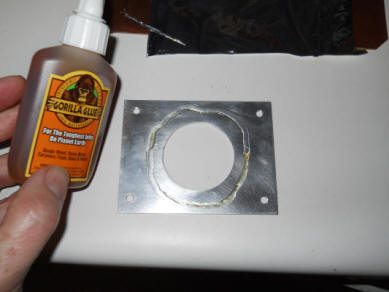
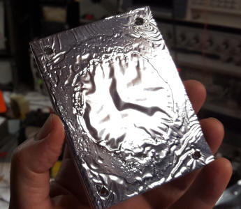
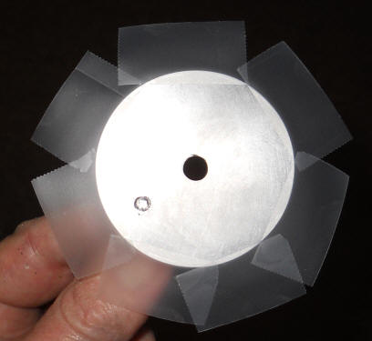
This next step is a little tricky. Cut a rectangle of metalized mylar from an emergency blanket making sure to find a piece with no wrinkles, at least in the area where the hole will be. Lay it metallization face up on a very flat surface. (Use an ohmmeter to determine which side has the metal.) Apply a thin but continuous bead of Gorilla Glue in a ring to one side of the metal plate with the smaller of the two large holes. It wouldn't hurt to "huff" on the glue as though you were cleaning your glasses or fogging up glass; the glue cures in the presence of humidity and you're about to seal it in a fairly airtight place. Turn the plate over and carefully drop it down onto the mylar. Try not to move it around much. Now, here's the experimental part! Originally, I let the weight of that single plate set the tension in the mylar but I think more tension is advisable (see update below). So, find a couple of modest weights to rest on the ends of the plate or possibly use an inverted drinking glass. The glass will let you observe the foil for the next step. I would only add a few ounces at most - maybe a cocktail glass.
With the weight in place, use your thumbs and fingers to firmly pull the four corners away from the center. The foil should look perfectly flat in the center. I think you can already see a wrinkle in the photo below. Don't settle for that. Resting the heels of your hands on the table, gently release the tension by lifting your fingers straight up. The weight and the viscosity of the glue will now set the tension. After a few seconds add more weight but make sure to go straight down.
It's important to give the glue plenty of time to cure. Don't try to fold over the edges until the next day. The next day, cut the excess mylar so that ears can be folded over and taped down. This is the sound input side and the grill piece will press against the tape, forcing the metallization to make contact with the aluminum. By the way, it's important to avoid poking the diaphragm with your finger from this point forward. If you do, consider replacing it - it must be very, very flat. Don't worry if a little Gorilla Glue bubbles up around the edges of the hole. Don't pick at it!
Very carefully cut little x patterns in the mylar and tape to expose the four corner holes. I didn't find that I needed to remove the material but it wouldn't hurt. Two details are of importance, the flatness of the diaphragm and electrical contact between the mylar and metal plate. Perfect bolt holes aren't important and mine ended up with a bit of a tear in one corner - no big deal.
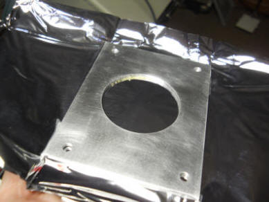
Recently I discovered that the mylar had wrinkled over time rendering the microphone less effective at high frequency. (Surprisingly it still worked at very low frequency.) I repaired the diaphragm with a superior method that I recommend for the original construction. Here's how it looked after a couple of years of service:
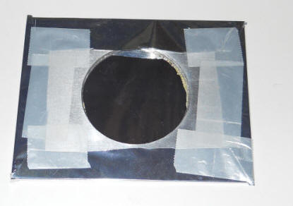
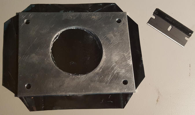
Disassembling and repairing the microphone was surprisingly easy. Unscrew the four bolts and the mylar diaphragm assembly is in your hands. The rest of the microphone remains intact. I cleaned off the mylar and glue to start over (try a razor blade). This time I stretched the mylar tight by taping it to a table with the metallization face-up:
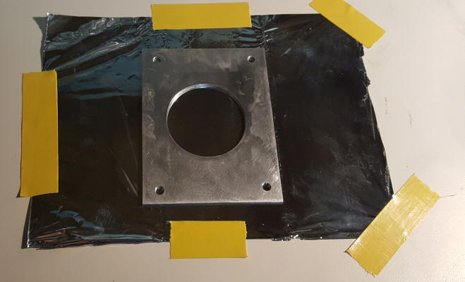
Start in one corner and pull the mylar tight when taping down the adjacent corners. Add more tape until the mylar is perfectly flat in the center with plenty of tension. The microphone is so "crazy" sensitive that an extra-tight diaphragm won't hurt and it should last longer. This time I used "Super" glue (cyanoacrylate) as my Gorilla Glue had hardened. I applied a ring of the glue to the aluminum about a quarter inch away from the hole, stood the plate on one edge, lowered it carefully, and pressed it against the mylar with considerable force. I added a weight and let it sit for about 30 minutes (just for good measure):
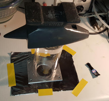
That's a drinking glass with an upside-down anvil on top. After the glue had plenty of time to set, I cut away the excess mylar:
I left enough length to wrap the mylar over to the input side of the metal plate. Ordinary scotch tape holds the mylar against the aluminum as before. The cover plate will push on the tape, forcing the mylar to make electrical contact with the aluminum plate. Sadly, I saw the finish line and forgot to take a photo but the mylar is very tight and perfectly flat. The glue spread out nicely and the foil looks "welded" to the aluminum. One problem is that the seal between the mylar and the styrene glue is spoiled when you rip off the old diaphragm. Run a thin but continuous bead of something like silicon rubber around the edge of the mylar face. Stay near the edges but stay inside the screw holes (they'll leak, too). When the mylar is pressed agains the pickup plate, the silicon rubber will form a new seal. Don't get the silicon rubber on the styrene. Use as little as practical but make sure to have a continuous bead.
End of Update
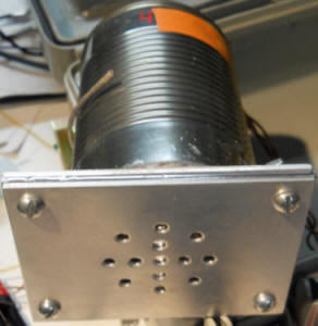
You can bolt the three plates together at this time. First bolt the grill piece to the diaphragm piece. Don't over-tighten but be firm. Then affix the pickup plate with four nuts:
You will note that I added a terminal strip to hold the electronics. I drilled and tapped a hole in that plate and made sure the bolt didn't protrude through to the other side - VERY IMPORTANT. You can choose some other way to hold the few parts. For example you could epoxy a small piece of PCB material sticking straight up like the terminal strip. Stay close to the hole since a can has to fit over everything.
Drill and tap a hole in the cutout you saved from the bigger hole and mount any sort of solder lug with a bolt that doesn't protrude all the way through:
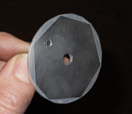
Apply pieces of scotch tape to form a single-thickness spacer along the edge of the disk. I think I see a place where my tape overlaps - avoid that. Gaps are fine; this is just a spacer. You can flip the taped disk over and use good scissors to easily trim the tape. I'm holding the disk by grasping the solder lug. The lug is how electrical contact will be made to the pickup plate.
Now it's time to make homemade Q-dope unless you already have some. Dissolve styrofoam shipping peanuts in MEK available at the hardware or paint store. Don't use other solvents.
It foams up a bit but the bubbles don't seem to hurt anything. I suppose one could wait for them to clear but I didn't. Make it fairly thick - use lots of peanuts. One concern is that the styrene will leak under the sense plate and touch the diaphragm. Put the pick-up plate into position, centering by eye, and paint a light coat of the styrene glue in the gap with a soft paint brush. I'd do that a couple of times over a couple hour period. After those coats have dried fill in the gap with more of the glue. The styrene will solidify and hold the disk in place. Don't try epoxy or anything else unless you are very, very sure of what you have chosen. I'm skeptical. : ) Most materials are simply too conductive. This stuff does the trick.
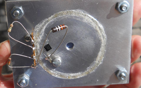
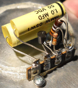
I was fiddling with circuits on the right but you can see how I've filled in the gap with foamy Q-dope. I'll discuss possible circuits later but a simple circuit is shown below. Basically the gate of a microphone JFET like the J201 goes directly to the pickup plate as does a high-value resistor. In this case it's a 13 gigohm resistor (brown orange white!) The capacitance of the plate and that resistance set the low end of the electrical frequency response. 10 gigohm resistors are readily available for a couple of bucks - see my comments below regarding the electrical bandwidth.
Make sure absolutely nothing else touches the center plate! The other end of the 13 gigohm goes to the far-right terminal which is "ground." A 10k source resistor also goes to ground from the third terminal. That's the output terminal. The drain is the second terminal and it gets Vcc. The first photo shows a wiring error corrected in the second. I've moved the leftmost leg of the 1 uF to the second terminal to bypass the drain to ground. The far left terminal is electrically connected to the outer can which is biased up to Vcc. That's a 2.2 uF capacitor below the 1 uF that connects across Vcc and ground.
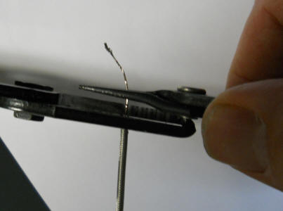
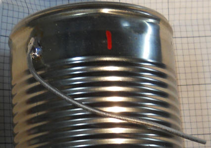
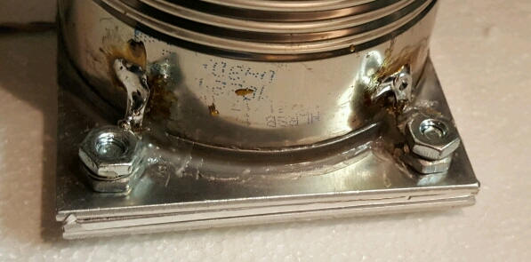
Find a way to add a hermetic connector to a soup can. I've used an old-fashioned header like those used on military relays or oscillators but a watertight connector would also do. The can needs a calibrated leak, and a slow one at that. Here's a nifty trick for adding a very, very slow leak to the can. Cut a few inch length of semi-rigid coax like this RG-405 and pull out the center conductor. I held back the teflon center insulator with wire strippers and pried up the center conductor until it broke loose and started coming out. You end up with a very narrow straw. Drill a hole in the can and solder the braid as shown below. The longer the tube, the slower the leak. I think the length shown is plenty, maybe 3 inches. You can imagine it would take quite a while for pressure from such a large can to discharge through that. Affix the can to the metal plate with silicone caulk or rubber. The can will not be centered over the pickup plate but will be off to one side to make room for the electronics. Just make sure the lip of the can doesn't land on the styrene. Do a careful job; it must be airtight. I added long solder lugs under the two screws close to the can and soldered them directly to the can to help hold it in position. If you don't do something similar, run a wire from the can to the terminal connected to the plates - the can and plates connect to Vcc.
The last photo shows another hole with orange tape covering it. That "breather" hole is necessary to let out glue fumes that, somehow, make the styrene insulation a bit conductive for a while. But it turns out that the hole is quite handy for testing. The photo below shows the difference in ambient noise with the tape removed and in place:
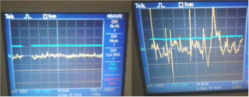
Clearly the microphone is working. It's a nice "sanity check."
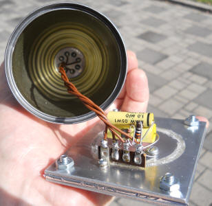
The microphone is finished but now steps must be taken to vanquish - to the extent possible- the ever-present noise from wind gusts. Step one is to enclose the microphone in a small 6-pack styrofoam ice chest. I made my own styrofoam case:
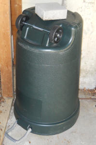
I used styrofoam spray adhesive and silicone caulking to seal it but I did not seal the wires going from the microphone to the phone jack. The box needs a breather hole, too. (Behind the microphone out of view is a freshly baked large desiccant bag.) Wind hitting this case will cause pressure changes inside so another layer or two is a good idea. I simply put this thing under a plastic trash can with a rock on top and that's under a patio. You might add a smaller trash can in between. The air inside the microphone case needs to be absolutely still.
The sensitivity of this microphone is quite high, absurdly high really. I initially watched the output on a scope with no amplification. But I want to add an amplifier at the microphone for driving the cable as it tends to pick up noise as-is. I'll be discussing the electronics in further detail in the future. A tighter diaphragm will lower the sensitivity a bit and improve the high frequency response plus add to the usable lifetime.
I'm using Spectrum Lab to observe the infrasound spectrum but a scope is also interesting for watching the large pressure swings from passing planes, trucks, etc.
Below is a helicopter making circles off in the distance. At the very bottom there's the "fires of hell" where there's constant noise from cars and trucks pushing air around (around 0.1 Hz).
Here's a spectrum centered at zero spanning about +- 0.7 Hz. I'm pretty sure the surges are vehicles passing on a nearby highway. The constant red line is the ever-present background noise rolled off by the electrical response of the microphone circuit (-3 dB at about 100 millihertz). It's symmetrical due to the conversion from low frequency up to 1 kHz; just ignore the bottom half. This stuff makes the scope trace bounce around quite a bit.
Okay, this is definitely a helicopter detector:
The helicopter was circling off in the distance and the backwards integral signs are due to the doppler shift of the rotor's frequency. All such vehicles exhibit a high frequency at first. As they approach, the frequency is shifted high.
I used a 13 gigohm resistor to bias the JFET and working against the 100 pF diaphragm capacitance I calculate a -3 dB frequency of 120 mHz. That seemed a bit high to me considering the microphone mechanical response is probably well below that. Also, the bigger that bias resistor, the lower its noise contribution at a particular frequency above cut-off. (The capacitance rolls off the resistor noise faster than it increases due to resistance at a particular frequency.) HOWEVER, I did a quick experiment and determined that it's probably a good idea to leave things as-is. That's good news for the experimenter since 10 gigohm resistors are fairly cheap at Digikey and Mouser. It turns out that the background noise increases sharply at the low frequency end of the spectrum, faster than the response of the microphone rolls off. And, the background noise is far above the electronic noise. Here's a spectrum plot showing the microphone response with and without that breather hole covered with tape. That's 20 dB per division.
It's clear that the electronics is not contributing significantly to the noise down to a fraction of a Hz. It's true that 100 millihertz is barely visible on this plot but another test I did with the oscilloscope suggests that there's at least a 20 dB gap for frequencies well below 50 millihertz (judging by the peak-to-peak wander over a period of many minutes). Over that time period the trace looks pretty dead with the hole uncovered and it "comes alive" with the hole blocked. The electrical roll-off actually helps the microphone cope with the very large signals down there. I think if I were to increase that resistor by a factor of 10, the electronics would spend a lot of its time overloaded. So, 100 millihertz is probably a good electrical bandwidth to use. Here's the time domain signal from the mic. after a 1 Hz low-pass, 0.05 Hz high-pass and 20 dB gain with the scope set to 50 mV per division and 5 seconds per division:
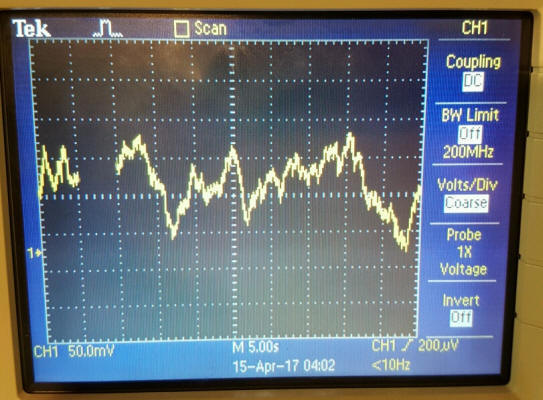
That's outside ambient noise. It would "flat line" if I were to open the breather hole.