
This converter shifts the VLF/LF bands, from below 20 kHz to over 350 kHz to the shortwave frequencies, determined by the selected crystal. In this prototype, the crystal frequency is 5 MHz, so the LF band comes out at 5.02 MHZ to 5.35 MHz, suitable for use with a shortwave receiver. Notice the lack of an expensive mixer or special IC!
Circuit and Component Notes:
|
A capacitor is connected across the input connector to achieve a total capacitance to ground of about 2000 pF, including the antenna cable capacitance. My prototype has a 470 pF because my antenna cable is quite long with about 1500 pF capacitance. See the end of this page for values to use with an antenna amplifier/buffer. | |
|
The 1 meg resistor and NE2 help fight charge buildup and voltage transients, and the transistor junctions are asked to handle the surges when the bulb fires. If you want a little more protection, connect a couple of silicon diodes from the base of the first transistor to plus and ground (diode cathode to plus, and the other diode anode to ground). Those diodes will conduct if the neon fires. I suspect the transistors can handle it, with one base-emitter junction conducting via zener breakdown. If lightning does hurt it, the transistors are cheap! | |
|
Use good capacitors for the two 1000 pFs on the input; either COG ceramic or mica would be fine. | |
|
The transistors aren't particularly critical and other types should work fine. | |
|
The output transformer isn't very critical and just needs to have a reasonable impedance at the output frequency. I used a random ferrite balun core with 18 turns, center-tapped for the primary and 3 turns for the output. You could get similar results simply winding turns on a short piece of ferrite. If you are familiar with RF transformers, a low-Q resonated transformer would be fine, too. If the radio has a 50 ohm input, you might want the primary inductance to be over about 6 uH to have adequate bandwidth. More is better. Less will work due to all the conversion gain the circuit provides. |
Improvements:
|
The experimenter might want to increase the emitter resistor from 15 ohms to soften the oscillation. Too big, and it will stop. Just right, and there will be less harmonic bleed-through. Not shown in the schematic is a 220 pF capacitor that I added to mine across the output connector to kill some of the higher frequency harmonics from the crystal oscillator. They weren't really causing a problem, but the capacitor reduces them on the 'scope without hurting the gain. | |
|
The balance of the transformer determines how much of the oscillator signal reaches the output. One could remove or add a turn to one end of the transformer to seek a better balance. A high carrier can kill the sensitivity of the shortwave receiver. The balance was fine on mine, reducing the oscillator signal to about 100 mV, p-p. Lower is better, but my receiver could reject that signal as close in as 10 kHz. |
Construction isn't critical as my point-to-point bird's nest illustrates:
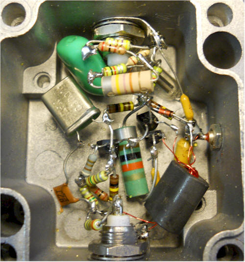
I added a few drops of silicon rubber to keep things from shifting! But the outside case looks good, at least! You can see one of the diodes mentioned above - I'd just leave them out.
I recently modified this converter to work with my active whip antenna instead of a vertical whip at the end of a long cable. That antenna buffer drives a terminated cable, providing a low impedance source for the converter. The new values also increase the bandwidth a bit:
Delete the selected capacitor to ground and replace it with an appropriate cable termination resistor (that is if you don't already have one somewhere else like I do; my active antenna drives more than one receiver so I have one termination resistor for all of them - not perfect but works well).
After the 0.1 uF from the antenna, change the 220 ohm resistor to 470 ohms and the choke from 470 uH to 270 uH or 330 uH. Change the two 1000 pF caps to ground to 470 pF and the 1k across them to 470 ohms.
Finally, change the 10 mH to 27 mH. The useful bandwidth will extend from about 10 kHz to 500 kHz.
This thing does have a lot of conversion gain so it's usually best to turn up the attenuator on your receiver a bit.