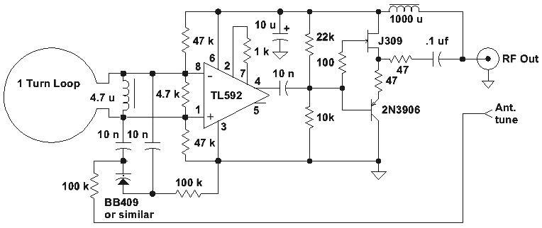
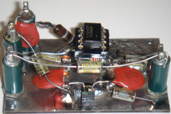
In the past, designs that incorporated an amplifier in the antenna were called "antennafiers" so perhaps this is a "loopifier". The differential amplifier solves matching issues and the varactor tuning gives excellent out-of-band rejection for even cheap receivers. I think the good common-mode rejection from the differential amplifier eliminates the need for a shield, too.
This active antenna for the shortwave band provides surprising
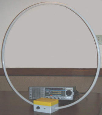
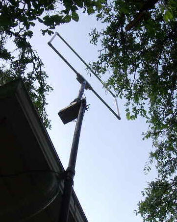
performance, even indoors. As the name implies, the main loop is made from a
Hula-Hoop with the metallic paint stripped off and a single turn of 14AWG copper
wire inserted inside the hoop. (There isn't any need to remove the paint;
mine was flaking and I didn't like the looks. Half way through I regretted my
decision!) These hoops are basically thin-walled
plumbing tubing with a water-tight connector holding the ends together. (Mine
was actually filled with water to make a "swish-swish" sound, supposedly.) The
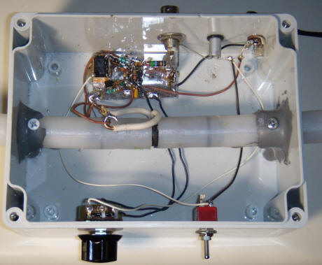
ends of the hoop pass through two holes in a plastic project box and are then
joined together. A hole was drilled in the middle of the original black tubing
connector to bring out the ends of the insulated house wiring (heavy white
wires). This single turn of wire has about 4 uH inductance. A couple of screws
and some epoxy holds the loop in position. The screws were added as an
afterthought, cracking the epoxy a bit, because the epoxy doesn't really adhere
to the tubing very well. The solid copper house wire is too stiff to connect
directly to the circuit so a couple of lengths of hookup wire were added. A
little piece of tinned copper circuit board material holds the circuitry. The
power is supplied by a molded power supply not shown.
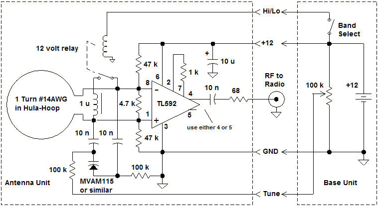
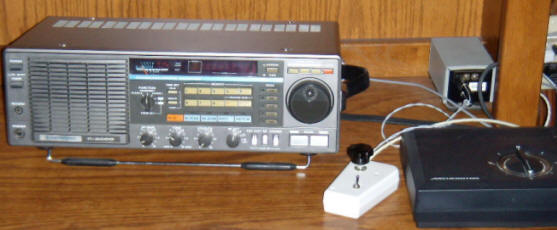
The circuit avoids matching issues by employing a high impedance differential amplifier, the TL592 or LM733 (which has a different pinout) connected directly across the loop. Even with the Q-killing 4.7k resistor, the impedance transformation is on the order of 100:1, an impractically high value for a broadband balun of reasonable cost. Even though the TL592 isn't the lowest noise amplifier ever designed and the resistor kills some of the signal, this configuration picks up so much signal that the circuit noise contribution is negligible! In fact, the amplifier is operating at a very low gain simply to avoid clipping and most signals push the signal meter well over S-9. I've never heard so many stations! The picture to the right shows the signal strength with the antenna tuned to WWV at 10 MHz with the antenna and receiver sitting on the kitchen table. That beats the nice vertical on my roof. Don't be misled, however; the antenna doesn't perform miracles. The atmospheric noise is also amplified so the signal-to-noise does depend on the location of the antenna and other conditions. Nevertheless, this indoor antenna has consistently outperformed my rooftop whip and when moved outside, it "blows away" the rooftop antenna, in some cases giving a strong signal when the whip gave no discernable signal at all.
(Without the Q-killing 4.7k resistor across the coil, the bandwidth was only 10 kHz at 5 Mhz. That's a Q of 500! There might be some future projects that take advantage of that.)
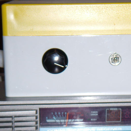
The indoor unit in the first photo combines both the "Antenna Unit" and "Base Unit" in one box .
Tuning is accomplished by an AM-band varactor like the MVAM115 or MVAM125. Suitable substitutes include the MVAM109, KV1560, KV1520, 1SV149, NTE618, BB112 or BB130 but the potentiometer voltage must be reduced to avoid exceeding some of those diodes' ratings. A 100k in series with the top pot connection should do the trick; select a value to give the maximum voltage the varactor can tolerate. Varactor tuning is recommended because longer leads for a mechanical capacitor may add resonances at FM frequencies, causing overload of the amplifier and nasty intermodulation at the output. The varactor should be kept close to the amplifier input leads to minimize the impedance at high frequency. A band switch activates a relay that connects a choke across the main coil for tuning above about 12 MHz. The schematic shows a 1 uH value but the best value will be determined by the choice of varactor and the tuning voltage range. My Hula-Hoop prototype above has two, 1 uH chokes in parallel to just reach 28 MHz but the square loop required 1 uH to tune to 30 MHz. It is pretty easy to tell where the antenna is tuned by observing the noise peaking on the receiver's S-meter. The original experiments were done at 15 volts and the extra voltage pushed the frequency to well over 30 MHz but I dropped down to 12 volts since 12 volt relays and power supplies are more common. The low end of the range is about 3 MHz and there is plenty of band overlap.
An outdoor version was built with ordinary PVC tubing in a square shape similar in dimensions to the Hula-Hoop (not critical). The stiff 14AWG copper wire was replaced with a heavy braid to make it easy to thread the wire through the square shape. The circuit is identical except that the potentiometer and band switch are in a separate box near the receiver (little white box) and a 4-conductor wire caries the DC signals to the remote antenna box (a PVC electrical junction box).
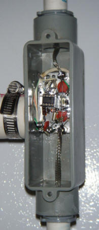
The relay was added after the photos of the outdoor box and board above. The wires coming down from the antenna include a cable with four-conductors to control the amplifier, a coax cable for the RF to the receiver, and a three-conductor cable for the antenna rotator.
The performance of the indoor antenna is good, moved outside on a flipped-over garbage can it is great, but the performance of this rooftop loop is spectacular! Simply tune the radio to the desired frequency then tune the antenna for maximum noise, switching the band somewhere around 12 to 15 MHz. (there is plenty of overlap). The Q is low enough that retuning is only necessary when moving from one band to another. In some areas lower Q may be desired to prevent amplifier overload. In only a couple of days I've heard stations all over the world including some "numbers" stations with S9 clarity.
Reader Minoe from The Netherlands has graciously provided a board layout designed by circuitz4u. Minoe says, "the zip contains both the Eagle files and the Gerber files. You can load the fines in Eagle for editing (http://www.cadsoft.de/freeware.htm)."
Thanks Minoe!
Here's another version of the circuit featuring a cable driver. This driver will reduce the gain loss due to heavily loading the TL592. The input impedance of the driver is quite high, and the output impedance is near 75 ohms. This version is set up to tune from about 9 MHz to over 25 MHz and other tuning components could be selected for other applications. The power for the circuit comes in on the coax and another 1000 uH and coupling capacitor would be needed on the other end, too, with the inductor going to the power supply and the capacitor going to the receiver. The power supply and receiver share the coax ground.
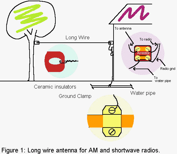
Fig. 2 shows how to add a loading inductor to the antenna in the event that a little more signal strength is desired. Most long wire antennas will be considerably less than 1/4 wavelength at AM band frequencies and behave as though a small capacitor is connected in series. The inductor resonates with this capacity and will increase the signal strength significantly. The required inductance range is from about 200 microhenry at the high end of the band to about 2 millihenry at the bottom end of the band for a 20 foot antenna.
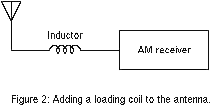
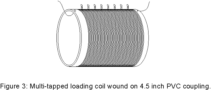
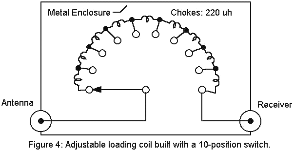
Fig. 3 shows how to build a programmable loading coil using a 4.5 inch PVC coupling (found in the plumbing supply area of the local home improvement store) and 22 gauge insulated wire. The coil is wound with 100 turns with taps brought out every 10 turns by twisting a little loop in the wire The total inductance of this inductor is about 1 millihenry so short antennas may need more turns for the lower frequencies.
.
A directional antenna may be constructed with a ferrite rod and amplifier as shown in fig.5. A ferrite rod 5/16 inches in diameter and 7 inches long was wound with 90 turns which gave sufficient inductance (about 300 uh) to cover the AM band without tuning and gave good reception well into the short-wave band. Experiment with whatever loopstick is available but larger is better.
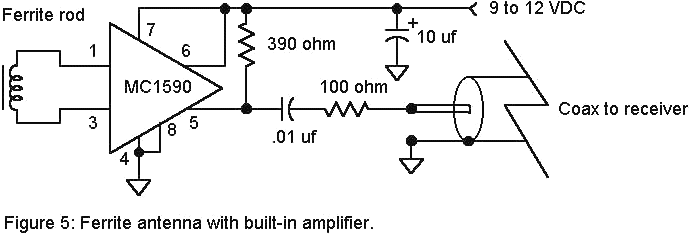
The MC1590 differential amplifier may be constructed on a small piece of copper-clad circuit board material using the copper board for ground connections. The amplifier should be mounted near the ferrite loopstick with the coax and power wire leading to the radio. No separate ground wire is shown since the coax shield will serve both purposes. The loopstick and amplifier may be slipped into a piece of 13/8 inch PVC with a cap on one end and a right angle coupling and pipe on the other (Fig. 6).
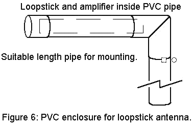
The vertical pipe may be secured to the outside wall of the house with clamps loose enough to allow the antenna to be aimed. The wires can simply hang out of the bottom of the tube without any seal or a little squirt of foaming urethane caulking could be used to keep out insects. Ground the coax to the cold water pipe for lightning protection if the loop is outside and high.
A totally different approach to low frequency antennas is shown in fig.7. A very short antenna can give amazing results, often performing as well as a long wire antenna if the proper buffer amplifier is added between the radio and the antenna. The electrical model of a short antenna includes a very small series capacitor - so small that little signal gets through and the required resonating loading coil is impracticably large. However, if the antenna is connected to a high impedance buffer with a very low input capacity, the antenna capacity will not attenuate the signal significantly. The amplifier must have good intermodulation characteristics so that phantom stations don't appear all over the dial and the antenna must be kept short to prevent amplifier overload. Don't connect this circuit to a long wire antenna unless you are curious to hear what radio chaos sounds like. Keep the antenna under a few feet in length, especially if strong stations are nearby.
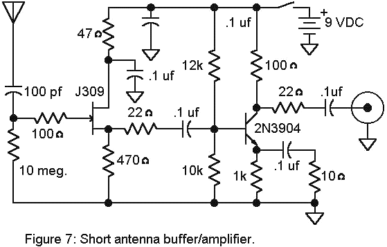
The N-channel JFET shown is a J309 but other similar parts may be substituted. (Possible subs include: J308-310, U310, 2N4857-4860.) The source voltage (on the 470 ohm resistor) should be about 1.5 to 5 volts. This source resistor could be changed to get about 4 mA of FET current using the formula: New R = V/.004 where V is the voltage on the initial 470 ohm resistor. This source voltage will change when the new resistor is installed to replace the original 470 ohm but the final current value is not particularly critical. Even lower current could be used (bigger R) to prolong battery life but the performance will begin to suffer somewhere below a couple of mA. The antenna may be a few inches to about 6 feet but avoid using longer antennas. With the values shown the buffer will work well from below 100 kHz to about 15 MHz which covers the frequency range where an antenna buffer is useful.
Here is how it works: The 10 megohm resistor sets the DC gate voltage to zero volts and the voltage on the source will rise to about 2 volts as the negative gate to source voltage reaches equilibrium with the source current. The FET is a very high impedance voltage follower which converts the high impedance antenna voltage into a much lower impedance voltage suitable for driving the 2N3904 amplifier. The base of the 2N3904 is biased to about 4 volts by the two base resistors and the 1k emitter resistor sets the collector current to about 3 mA. The amplifier has an RF voltage gain of about 10 which is set by the ratio of the 100 ohm collector resistor and 10 ohm emitter resistor. Lower gain may be achieved by increasing the 10 ohm resistor if the circuit is being overloaded by large signals but a shorter antenna is usually the best approach.
Notes:
Figure 8 shows an improved version of the short active antenna that will work well from below a few kHz to 30 MHz and is usable to over 100 MHz:
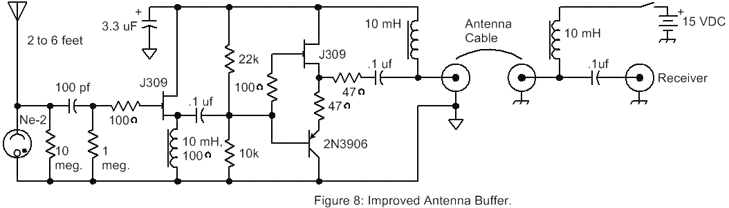
The first 10 mH inductor used in the prototype has about 100 ohms of resistance and that resistance is important in the source of the first J309. If you inductors are significantly lower in resistance, add a series resistor to total around 100 ohms. The other two chokes in the power supply should be below about 100 ohms, but lower resistance is fine. Lower value chokes can be used, but at some point, the low frequency response will suffer. For 100kHz and above, 1 mH is good. Also make sure that the lower value choke exhibits 100 ohms of resistance in the source of the JFET by adding series resistance.
The source inductor and complimentary output stage give the circuit good large-signal handling capability, but keep the antenna shorter than about 5 or 6 feet to avoid potential overload by strong signals. The power supply is indicated as 15 volts and 12 volts will work, but with slightly less signal handling capability. Higher supply voltage is also fine, up to about 25 volts.
Note: Don't test intermod with test signals above -10dBc; larger signals can overload the amplifier and such signal levels won't normally be encountered. I recently built a two-tone generator for intermodulation tests that produces two independent -15dBm signals. The circuit above produces a -65 dBc product at 1 MHz when driven by 4 and 5 MHz, -15 dBm signals. That's pretty decent. However, adjusting the power supply voltage can dramatically improve the performance. At 17.6 VDC, the prototype's distortion dropped below -90 dBc! It becomes a challenge to measure. The optimum power supply voltage varies from unit to unit. Others I've built had an optimum voltage as low as 7 volts. To increase the optimum voltage reduce the 22k (and vice-versa). In fact, you can choose your desired voltage first (say 9 VDC) then tweak the 22k for best intermod.
If you have two unusually strong stations tune a receiver to their difference frequency and adjust the 22k for minimum signal. (In most cases strong enough signals to cause noticeable IMD won't be present; one would need two signals well above 1 millivolt each to get a 1 microvolt product from the prototype running on 15 volts.) As a worst-case test I lowered the voltage to 12 volts, used an 8 foot antenna, and looked for the intermod from two strong AM stations, each showing -30 dBm on my HP3586 Selective Level Meter. I could see the noise floor of the measurement at the difference frequency, over 70 dB down. Atmospheric noise obscures any intermod. So, intermod isn't much of a factor in most settings.
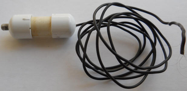
The circuitry was built into a short piece of PVC pipe with end caps:
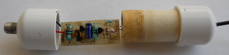
The RF connector and antenna wire were sealed with a little epoxy in each cap. The antenna wire is heavy insulated copper wire like that used in house wiring. The antenna is simply hung from a hook or string and the end could be pulled into the air by tossing a string over the branch of a tree. :
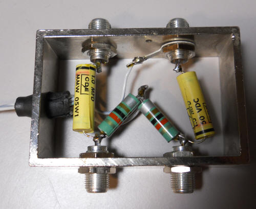
The box below distributes power to two antennas, including this one. Power comes in on the left from a regulated 12 volt molded power supply. The two inductors pass the power to the two antenna connectors at the bottom. 1 uF capacitors couple the antennas to the receiver connectors at the top. Even more active antennas could be accommodated by adding the appropriate parts.
This antenna significantly improves my weather radio reception at 160 MHz. It also improves the sensitivity of my Sferics Detector, operating below 100 kHz. For that, I just connected a clip lead from the output of the amplifier and wrapped it around the antenna of the Sferics Detector to lightly couple it. Here's a little video showing it in action. Notice the wire just loosely wrapped around the antenna.
For higher frequencies, a resonant antenna becomes feasible. For example, Fig. 8 shows a simple vertical ground-plane antenna which connects directly to 50 ohm coaxial cable without a loading coil or matching network.
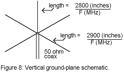
Using the equations shown, a 49 MHz antenna would have a vertical element 57 inches long and ground elements 59 inches long. The vertical element simply connects to the center conductor of the coax and the ground elements connect to the coax braid. The elements may be mounted on a small square of phenolic, fiberglass, or other weatherproof board material. Try not to let dissimilar metals come in contact or, if they must, coat the contact area with silicone rubber. One simple approach is to make the whole affair from PVC pipe with copper wire or tubing on the inside. It is often desirable to have a fixed-frequency antenna with directionality for monitoring a particular station or for installing on an antenna rotator. For example, if you live within a mile or two of a fast food restaurant you can probably pick up the little wireless microphones they use to take orders. You are probably wondering why anyone would want to pick up those signals (which are around 33 MHz). Hmmm. Well, it would be a challenge. Or, how about building a dedicated antenna to receive a distant weather transmitter instead. Or the police in a neighboring town, or a remote airport. Those sound a little better. (When my kids were small I thought of making a tricycle "drive-up" window with real audio from the local fast-food restaurant - never got around to it...) The point is that a directional antenna will give greatly improved performance for any of the signals on your scanner. Multi-element yagi antennas are a good choice for single frequency reception and log-periodic antennas give excellent multi-band reception. The construction of these antennas can prove difficult and purchasing a factory assembled unit is usually a preferable approach. A three-element yagi is not overly difficult for the more experienced hobbyist and several design references are easily found on the internet. A search using "3-element yagi" turned up nearly 600 hits including excellent design articles and commercial sources.
copyright 1995
updated 2011
by Charles Wenzel