
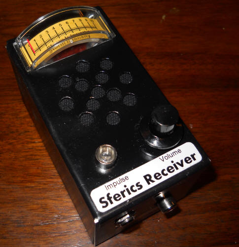
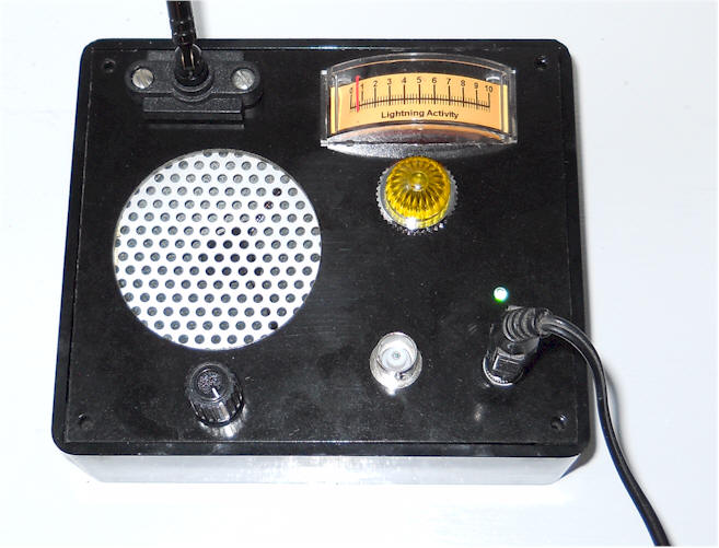
"Sferics" (also spelled "spherics") is short for atmospherics and refers to the crackling static in a radio produced by lightning. This receiver is tuned to an unused portion of the LF band and provides enough sensitivity to detect lightning activity for hundreds or even thousands of miles. Best performance is achieved with an external antenna, but just a few yards of insulated wire is sufficient. A short whip mounted on the unit will work fine for picking up local storms.
Starting to the left, a trap may be added by resonating a 470 uH or 1 mHy choke with a selected capacitor to eliminate strong AM stations, when using an outdoor antenna, especially an amplified antenna. The traps aren't necessary with a short antenna. (I like faint station bleed-through, simply to let me know it's all working properly.) The 220 ohm resistor between pins 2 and 7 of the TL592 may be changed to change the gain, higher values giving less gain. I started with 47 ohms but ended up with a 200 ohm pot turned all the way up. It's easy to have too much gain so start with a 220 ohm resistor. I've added a 33 ohm resistor in series with the 10 uF from pin 1 to 8 on the LM386 to reduce instability when the volume is turned up high.
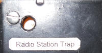
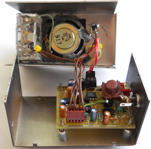
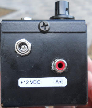
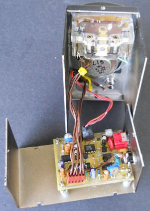
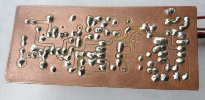
Bottom of Case
That big, brown part in the first photo near the power connector is a choke in series with the power line. It was found to be unnecessary and was removed, but a regulated power supply is necessary.
Use a good ceramic capacitor for the 2.2 nF capacitor but feel free to try other values, including the inductor. The values shown receive static at about 300 kHz, a higher value than my original receiver to dodge noise from cheap electronic ballasts throughout my neighborhood. Keep the frequency below about 350 kHz or you will have problems with AM band interference. Use a good RF capacitor; this value also "shorts out" higher frequency stations. That's the purpose of the 330 ohm resistor, to give the tank capacitor something to work against when rolling off higher frequency stations, especially strong FM stations You will note a 100 ohm resistor in the photos and that's adequate.
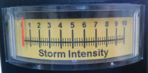
The 1N5711 detector is a biased detector with a twist. The detector has a long discharge time-constant that gives the output a ramp-like response to lightning pulses, with the length of the ramp being proportional to the size of the pulse. That causes the first LM358, acting as a comparator, to output a pulse with a width that is proportional to the received pulse height. The detector's amplitude-to-pulse width response also gives more powerful strikes a deeper sound, making it easy to tell what's happening simply by listening. You hear a "tick" for weak pulses and a deep "thunk" for big ones. I like how it turned out. Those pulses drive a lamp flasher and another op-amp averaging circuit for driving a meter. The tendency of the lamp to flash is easily modified by changing the 10k pot to ground on pin 2, with a lower setting making the light more sensitive. The 22k resistor determines how much each pulse affects the meter reading, and the 10 megohm determines the window of time that is averaged, lower values giving a faster response.
The schematic uses a 10mA current meter, but a voltmeter would also work fine. Expect about 3 volts at pin 7 when the lightning is "pegging" the meter circuit.
The LM386 needs care to prevent oscillation, because it has gain in the frequency range of the receiver. First of all, note the 4.7 nF at pin 3 is a little larger than normally seen, and the addition of the series 4.7k makes sure there is roll-off even when the volume control is all the way up. It isn't a bad idea to increase the capacitor to 10 nF if instability is encountered. Also, the output stabilization network is modified to block RF from getting into the speaker wires. I used a commercial part but you can simply wind 30 turns of enamel wire around the body of a 1/2 watt, 47 ohm resistor, or wrap four or five turns through a ferrite bead and connect that in parallel with a 47 ohm resistor. It would be a good idea to keep the speaker away from the input circuit and to twist the speaker wires together.
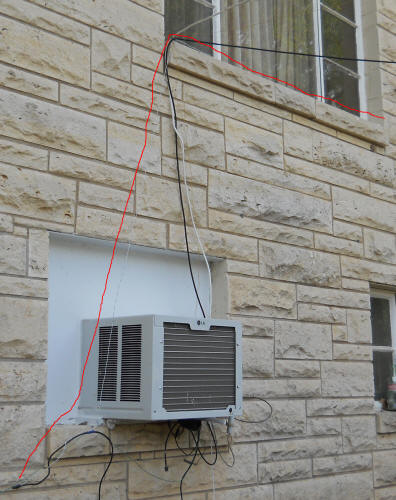
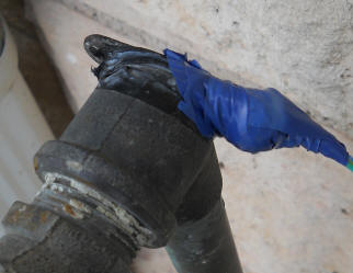
An outdoor antenna gives best results but it only needs to be a couple of meters long. The photo below has a red line drawn next to the antenna wire that runs from the end of a length of coax cable below the air conditioner up to a second-story window sill. It would be better if it were away from the house but it's pretty easy to pick up lightning that's only a couple of hundred miles away. Any more range and the unit would be excessively sensitive. In fact, be prepared to lower the gain of yours; it's not that great to hear every bolt that happens in the country. A ground wire runs from the coax braid over to a water faucet. This is a "temporary" antenna but I've had a similar antenna in use for years.
 |
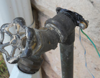 |
 The ground wire
and |
 |
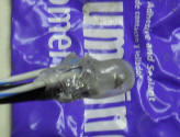
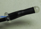 A length of heat
shrink |
Since these photos, I've connected the Sferics Receiver in parallel with my SID receiver to an Active Antenna. The gain was far too high. I had to increase the 330 ohm going to pin 1 to 3.3k and change the gain pot from 200 ohms to 2k.
I made boards using the ExpressPCB service, getting six boards from a single miniboard order (cutting the boards in half with a shear). Modify the file to accommodate your components or to make any desired changes. Here are links if you want to copy or modify these boards:
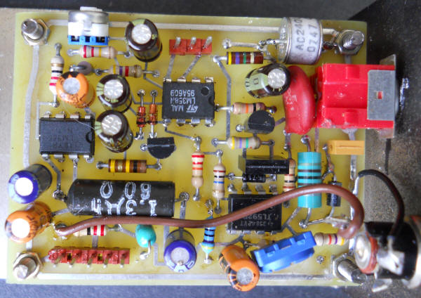
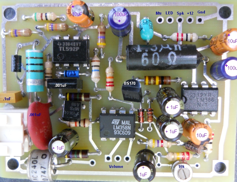
Here's the final configuration in my unit:
 |
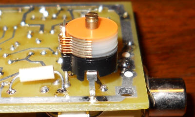
The AM band trap mounts on the back of the board and those pads could be modified to accommodate different trimmer and inductor styles.
|
 |
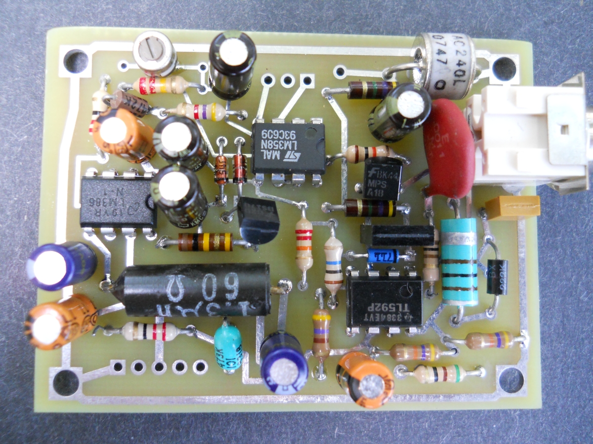
As is usually the case, I wish I had done things a little differently. The brown wire is for power. I didn't use the Molex connector so that the two halves of the case could be separated. It turns out that the board isn't easily removed from its section of the case. Also, I used small pads for the mounting holes so I had to find small nuts to prevent shorts; those could be larger. The blue pot is a gain pot for the RF amplifier and the white pot to the top, left is the threshold pot. The layout accommodates Molex connectors for panel-mounted controls but I should have included trimmer pot holes, too. Actually, a 220 ohm fixed resistor is probably fine for the RF amplifier.
Documentation is limited to a few high-resolution photos of the stuffed board. I don't have a parts list beyond the notations on the schematic.
![]()
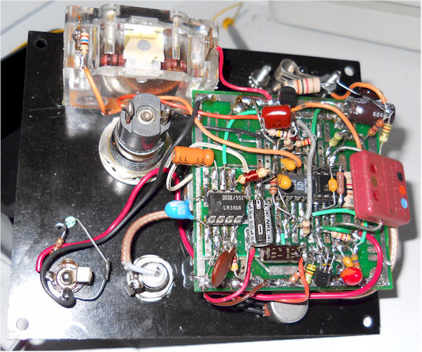
Here's the original unit and circuit:
![]()
Rajkumar from Nepal made a much neater version:
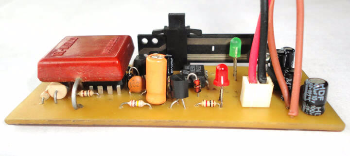
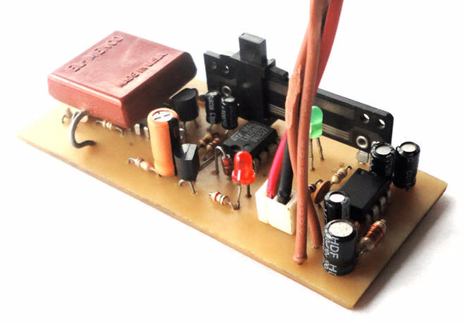
The PCB was made using the toner transfer method from a layout made using ExpressPCB. The results are quite professional!