And the intriguing "Sinitsa" modification
 |
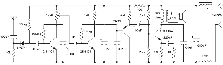
The Amazing All-Band Receiver is basically a diode detector followed by a high-gain
audio amplifier. This is not a multi-band receiver; it picks up everything at once! The
detector uses a biased Schottky diode for excellent sensitivity and bandwidth; the
detector will detect signals from below the AM broadcast band up to the microwave bands.
The number of interesting signals is surprising; it is fun to drive around listening to
the numerous strange sounds. By trying different antennas and locations, this receiver has picked up AM radio stations, FM stations, TV video (buzz), car lock transmitters, cell phones, and even the microwave oven (a whoosh-whoosh sound as the microwave spreader rotated). It isn't clear how FM stations are demodulated; perhaps the antenna Q is sufficient for slope detection. (See reader Karen's excellent theory.) Even the familiar buzz from a narrow-band FM pager transmitter has been heard - somehow. There are some mysterious signals out there, too! What is that occasional descending whistle over by the highway? Some vehicles emit a curious buzz, too. If you hear a mysterious click-click now and then, its your cell phone! Don't expect to tune in international shortwave stations. This receiver is for strong, local sources. The advanced experimenter will find it useful as a detector section for low power tuned receivers. Karen recorded the sound of a U.K. cell phone tower! |
Other signals that should be easy to receive include in-flight aircraft transmissions (this passive receiver will not interfere with communication/navigation systems), CB radio transmissions, amateur transmitters, "bugs", wireless networks and devices, radars, radio control transmitters, certain security/alarm systems, and even unexpected oscillations in your next circuit.
A short, perhaps 6", antenna is a great general-purpose length for general listening but trimming the length for the a desired band will give better sensitivity. For the antenna connection, use an RCA or similar connector with the ground connected to the battery negative in case you want to try a loop antenna. Loop antennas (loose end connected back to ground) work especially well for single frequencies and a tuning capacitor may be added across the loop. This detector circuit will also work well as a crystal radio, even at higher short-wave frequencies with the addition of a simple tuned circuit. Add a 10 to 100uH choke in series with the antenna near the receiver to keep out the higher frequency signals when listening to AM stations and connect the diode to a fairly high impedance tap on the tuned circuit since the diode impedance is high in this circuit. The 100pF capacitor and 10k resistor are not needed as long as the tuned circuit provides a DC path to ground for the diode. (See Crystal Radio Circuits for tuned circuit ideas.)
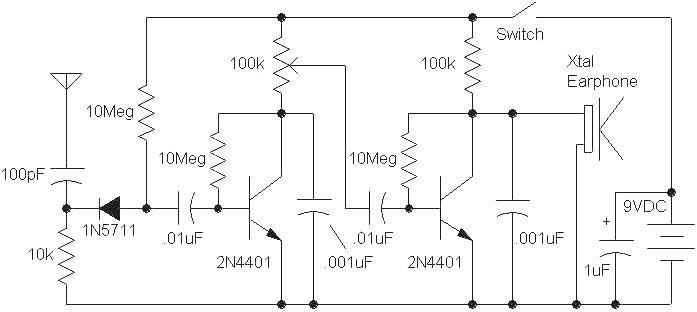
The above schematic shows a 100k volume control but the signals usually aren't loud so this component may be replaced with an ordinary 100k resistor. The .01uF capacitor would connect directly from the collector of the first transistor to the base of the second. This amplifier is non-inverting so a feedback squeal will be heard if the earphone wires are too near the antenna. Reduce the 100pF in the antenna if feedback squeal is a problem. The circuit draws only about 125uA so battery life is excellent. The circuit is designed for a sensitive crystal earphone and cannot drive most other types of earphones. One notable exception is older sensitive dynamic headphones which are rare treasures. To drive a lower impedance earphone, say a 60 ohm type, lower the last transistor's collector and base resistors from 100k and 10Meg to 1k and 100k but remember that the battery current will be much higher. An 8 ohm earphone will require a different output stage for satisfactory performance.
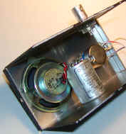
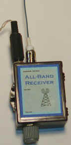
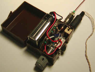
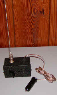
An inexpensive plastic box makes a great housing. The unit below employs a couple of pieces of tinned circuit board to hold the circuitry and to act as a battery holder. The tab on the circuit board assembly is soldered to the unused bottom row of pins on the power switch to hold it in place. A few drops of epoxy on the bottom side could serve the same purpose. Don't forget some fancy artwork for the front of the box!
 |
 |
Any high-impedance high-gain audio amplifier circuit will work with the basic diode detector so feel free to experiment. Remember to leave the 10Meg bias resistor for the diode and couple the amplifier through a .01uF capacitor. If you prefer an IC to discrete transistors, take a look at https://www.techlib.com/electronics/aircraft.htm. Just replace the tuned-circuit with the 10k and 100 pF as in the above schematic. Or, alternately, you can add a tuned-circuit to these receivers to make a sensitive diode detector receiver for a particular band using the aircraft receiver setup.
Here is another idea: Find an old AM/FM radio with an antenna to house the receiver. The case will have a nice antenna, speaker, earphone jack, battery holder, switch and volume control - almost everything! Even better, with a little effort you can remove the RF portions while saving the audio amplifier. The audio is usually applied to one end of the volume control and you can get away with only the first transistor amp in the above schematic. Couple the collector of this transistor to the potentiometer with a 10 uF capacitor with the plus end going to the collector. It would be a good idea to replace the 100k pot in the collector with a 33k fixed resistor and reduce both 10 megs to 3.3 megs or so, especially if the radio runs on two AA cells which is typical these days.
![]()
Here is a version of the all-band receiver for the car. The following circuit can be tricky due to the very high gain combined with the high speaker currents which is a sure recipe for stability problems. Be warned that making it work right may be a challenge if you are a novice. It makes a great workbench companion, watching for undesired oscillations in your latest creation.
The circuit is similar to the two-transistor version but the second stage uses lower resistor values for driving a PNP emitter-follower. The emitter-follower provides enough current to drive a transformer-coupled class-A power amplifier that can deliver several hundred milliwatts to the speaker. A transformer-coupled class-A amplifier was chosen for a couple of reasons. First, the transformer provides an efficient match to the speaker and lowers the audio current flowing in the circuit ground. Second, the class-A amplifier is simple, performs well and, since the circuit operates from the car's battery, a little inefficiency is fine. Class-A audio output stages should not be overlooked by the experimenter! The gain of the output amplifier is reduced by a 10 ohm resistor in series with the 220uF emitter capacitor because the overall circuit gain is so high. If you experience stability problems, increase the value of this 10 ohm resistor; don't worry, there is plenty of gain left! The 2N2219A does dissipate about 1/2 watt so some heat sinking is required. Power transistors will work well, including TO-220 types which would not need a heat sink; try a TIP41, for example. Truthfully, I wanted an excuse to use the cute little black heat sink.
Placing the volume control in the DC path of the first transistor causes some noise when adjustments are made so it may be better to replace the pot with a fixed 100k resistor and to AC-couple the potentiometer to the collector.
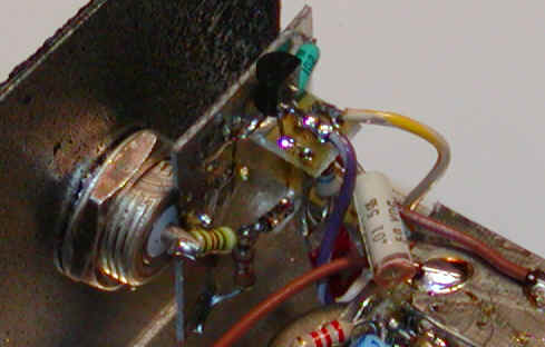
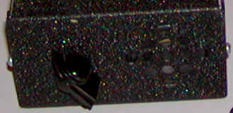
The unit is constructed in a "black crackle" metal housing with a BNC connector for the antenna:
 |
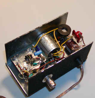 |
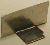
The audio transformer is the metal can in the picture above but any 500 ohm to 8 ohm miniature type will work. The output transistor has a black heat sink attached and is mounted to a miniature terminal strip. The red blob is one of the power chokes before it is secured to the capacitor with some hot-melt glue. Notice that the circuit is separated into three sections to reduce feedback. The output stage is directly connected to the incoming power leads, and the rest of the circuit has a filter consisting of a 100 ohm resistor and 22uF capacitor to reduce the possibility of feedback via the power supply. The diode detector and first transistor are mounted directly on the BNC:
 |
Before circuits are installed: |
This gadget has enough gain to hear the internally-generated component noise with no antenna attached in a noisy car. After the unit was placed in a spot in the car relatively free from ignition noise, all sorts of strange sounds were detected. A shorter antenna is favored due to the abundance of FM and TV stations - try 2 or 3 inches. There are some common sounds: The penetrating buzz that sounds like 60Hz line noise is from TV stations, the really loud hiss means you are passing near a digital cell phone tower, the gaggle of music and voices are FM stations, other buzzes and tones are probably from digital networks, nearby cell phones, and other wireless devices but who knows! Get within a half mile or so of an AM transmitter and you will be reaching for the volume control.
A high fidelity AM radio was realized on the workbench simply by connecting the BNC through a 10uH choke to a tuned circuit consisting of a 120uH choke in parallel with a large variable capacitor. The antenna was about 3 feet long. This project makes a great universal detector for a variety of bench experiments. The rough black finish really looks great, too.
![]()
Here is an email from a reader regarding FM detection:
![]()
Here is a modification that uses an audio amplifier IC sent in by a reader (Paul Beaumont MIScT G7VAK):
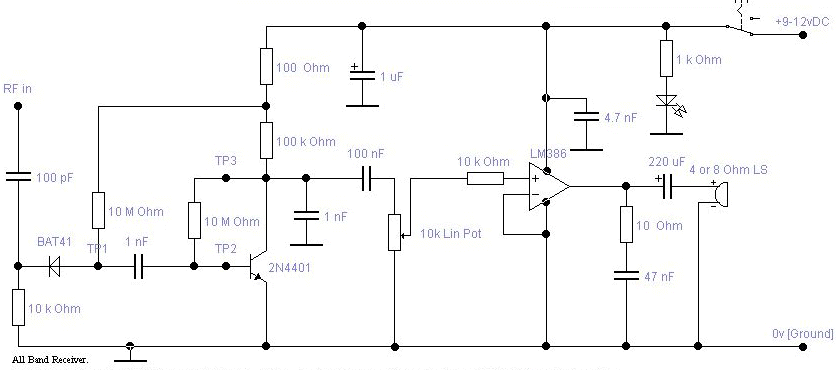
Supply voltage is 9 or 12 volts DC from a regulated supply. A battery is not used as consumption can rise to around 75mA in strong signal conditions. | |
Amplifier is LM386 with an adequate gain of 20. Input from 10k pot and series 10k resistor to pin 3. Pin 2 and 4 to 0v line. | |
To raise gain to 50 connect a 1.2k resistor and 10uF capacitor
between pin 1 and pin 8 [- to pin 8]. | |
Output is via pin 5 and a 220uF capacitor, [+ towards pin5] 25v wkg or better. LS is a 4 or 8 Ohm miniature loudspeaker. | |
Supply to LM386 is via pin 6 which is strapped to + rail but with a 4n7 decoupling capacitor near to the chip. | |
Various lengths of antennae can be used and for experimentation a parallel tuned circuit can be connected between the RF input and the 0v [Ground] rail. | |
If a BAT41 is not available a BAT85 can be used. 1N5711 and 1N6263 are also suitable. |
| Test Point Voltages [ no signal, Fluke 83] |
| TP1 circa 100mV |
| TP2 circa 540mV |
| TP3 circa 2.95V |
Paul Beaumont MIScT G7VAK
Thanks for the IC version, Paul!
![]()
Here is an interesting version used for cellphone detection by Paul Smith (Indiana University Physics), ptsmith@indiana.edu :
http://www.physics.indiana.edu/~ptsmith/cell/
![]()
An anonymous contributor submitted this fascinating modification:
This modification is based on a Soviet Cold War device, the Sinitsa. A carrier frequency, just above the audio range, is added into the incoming signal to produce a host of sidebands. The result is that just about any signal, even a dead carrier, will produce a detectable audio output. I think the audio from the oscillator could be injected into the bottom side of the 10k bias resistor, eliminating the need for the 10 uH choke. Maybe the 10k resistor is replaced with a 10k trimmer and the wiper of the trimmer goes to the op amp through another 10k in series with a 1 uF cap to save a little current. Alternately, add a 1k in the ground leg of the 10k and hook the wiper of the pot there. It might be interesting to make the frequency of the injected square wave variable and with very sharp edges, perhaps from an AC logic device. Lots of experiments to try here!
![]()
Upon reading a description of how the original Sinitsa works, I've come up with a new approach. The original Sinitsa used a diode up front to modulate any RF signals, basically gating them on and off. Then, after band-select filtering, an ordinary diode detector produced an audio signal from the now-modulated RF. I had originally thought that harmonics from the edges of the square wave were mixing with the RF signal directly in the first stage. I came up with a somewhat different approach that I think is functionally similar but doesn't require any "handling" of the RF:
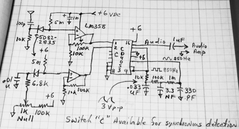
In my version, the analog switch toggles between the DC from the detector diode and a reference diode. To the extent that the reference diode tracks the detector diode (mostly thermally) this should produce about the same result as turning the RF on and off to the detector diode. (In other words, when the RF is off, both diodes should produce the same voltage.) I don't "touch" the RF before the detector and I can null out a steady background RF level. The oscillation can be stopped by grounding pin 11 of the CD4053 with a toggle switch and the circuit will then behave like original All Band Receiver. The details of the audio amplifier haven't been worked out but a simple LM386 is probably sufficient. I might use an op-amp stage of some sort as a preamplifier if I want to synchronously detect the signal for driving a meter (using switch "C").
Note the snazzy way I made the CD4053 toggle itself. That might have some interesting applications for lock-in projects. It's basically a DPDT self-toggling switch.
I used the 5082-2835 but any RF Schottky diode should work including the common 1N5711. Here's a fun application: The Bug Duster. The transistor amplifier could be replaced with an LM386. It turns out that not much gain is needed. If you try the LM386, add a switch to disconnect the capacitor between pins 1 and 8 to lower the gain for "bug sweeping." Otherwise it will simply be too sensitive.