The crystal radio gets its name from the galena crystal (lead sulfide) used to rectify the signals. A "cat's whisker" wire contact was moved about the surface of the crystal until a diode junction was formed. The 1N34A germanium diode is the modern substitute for galena and most other germanium small-signal diodes will also work well. Silicon diodes are not a good choice because their much higher barrier potential requires larger signals for efficient rectification. Certain silicon Schottky diodes with low barrier potential will work well but most small-signal Schottky diodes will not perform as well as a garden-variety germanium diode.
|
The circuit is quite simple but many pitfalls await the novice. The first precaution is most important! The crystal radio works best with a long, high outdoor antenna but the beginner may not fully appreciate the danger of bringing such a wire into the house. Lightning strikes to the antenna will probably destroy the crystal radio but if precautions are not taken, much more damage will result. The best strategy is to incorporate a commercial lightning arrestor with a straight, heavy gauge ground wire leading down to a buried water pipe. It is not sufficient to disconnect the antenna from the receiver during thunderstorms.
Other pitfalls are less dangerous and relate to the receiver's performance. A common mistake when building a crystal radio is to load the tuned circuit excessively. The Q of the tuned circuit must remain high to give selectivity or strong radio stations will all mix together. A good design will usually have low-impedance taps on the inductor for connections to the antenna and diode as shown in the schematic. A long wire antenna with a good ground connection will connect to the lowest impedance tap whereas a shorter antenna with no ground connection may connect to a higher tap. The diode may be experimentally moved to different taps and even across the whole coil for maximum sensitivity. The antenna and diode connection may be made with alligator clips for easy experimentation.
 |
Another potential problem area is the earphone. Not all crystal earphones are sensitive and the experimenter should test a few to get a "good" one. High impedance dynamic earphones are a bit more reliable and can give excellent results. Try an old telephone receiver or a modern portable tape player headset (some are high-Z and fairly sensitive). Low impedance earphones like those used with many portable radios will not work at all. A simple test is to hold one earphone wire between the fingers while scraping the other lead across a large metal object like a file cabinet. If static is heard in the earphone it will probably work well with the crystal radio.
The variable capacitor is often connected incorrectly. Make sure to connect the rotor to ground and the stator to the "hot" side of the coil. Otherwise, the radio will detune when the capacitor knob is touched. If detuning is noticed then try reversing the connections.
Some experimenters are tempted to omit the 82k resistor which discharges the capacitor on the theory that it wastes precious signal power. With a typical germanium diode, this little "improvement" may work somewhat but only because the diode has significant leakage and the performance will not be predictable. A dynamic earphone may be DC coupled eliminating the need for the resistor.
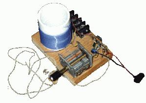
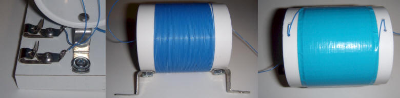
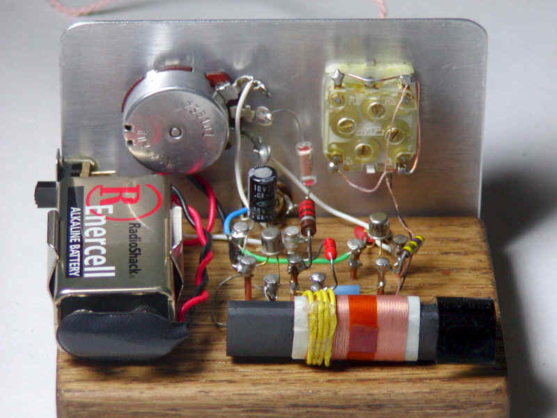
The coil may be wound on a 1.5 inch PVC pipe coupler as shown in the drawing. These typically have an outer diameter of about 2.2". Drill two small holes at each end to secure the ends of the coil. The wire type is not particularly critical but select a gauge and insulation so that the 65 turns cover about 2/3 of the coupler. An excellent choice is 30 AWG "wrap" wire from Radio Shack. The prototype uses this solid conductor wire with blue insulation. This wirewrap wire is available in 50' lengths on little spools and about 37' will be needed. A "loopstick" coil may be used in place of the coil shown. These coils have an adjustable ferrite core for tuning so a fixed value capacitor may be used in place of the variable capacitor shown. The coil, capacitor and a terminal strip for the other parts may be mounted to a small wooden board. (See photo of receiver with transistor amplifier below.)
 |
If a metal chassis is used then the coil must be mounted horizontally and above the metal to prevent unacceptable loading.
Here are some alternative construction ideas:
Fahnestock clips make excellent connectors for the antenna and ground wires. The coil may be mounted above the board or chassis with angle brackets by adding another bend, as shown below. The windings may be quickly secured with a single layer of colored "Duck" tape that is now available in more attractive colors than gray or black. The taps to the coil can be located at the rear, near the bottom so that the unavoidable bulges in the tape don't show. An ordinary piece of wood may be quickly finished by applying adhesive-backed PVC film intended for kitchen cabinets. Just stick it on and trim flush with scissors.
An amplifier may be added to boost the audio level as shown below. The current consumption of this amplifier is quite low and a power switch is not included. Disconnect the battery when the receiver is stored for long periods.
 |
� 1995, Charles Wenzel
Note: You may use the transistor above as a sensitive detector eliminating the need for the 1N34A diode. Simply leave out the diode, the 0.001 uF, and the 82k resistor. Connect the negative side of the 1 uF directly to the coil. Change the base resistor from 10 meg. to 1 meg. and change the collector resistor from 100k to 10k. Now add a 0.01 uF from the collector to the emitter and the modifications are complete. This detector is quite sensitive and will be overloaded by very long antennas! Use a shorter antenna or a coil tap very near ground if significant distortion is noticed. The circuit draws about 1/2 mA. |
Here is a simple audio amplifier using a TL431 shunt regulator. The amplifier will provide room-filling volume from an ordinary crystal radio outfitted with a long-wire antenna and good ground. The circuitry is similar in complexity to a simple one-transistor radio but the performance is far superior. The TL431 is available in a TO-92 package and it looks like an ordinary transistor so your hobbyist friends will be impressed by the volume you are getting with only one transistor! The amplifier may be used for other projects, too. Higher impedance headphones and speakers may also be used. An earphone from an old telephone will give ear-splitting volume and great sensitivity! The 68 ohm resistor may be increased to several hundred ohms when using high impedance earphones to save battery power.
 |
To use the circuit as a general-purpose amplifier, apply the input signal to the top of the potentiometer. (Leave out the diode and .002 uF capacitor.) A higher value potentiometer may be used for a higher input impedance.
� 1995, Charles Wenzel
For the more experienced hobbyist...
One of the best places to add a transistor to a simple crystal radio is at the front end in the form of an RF amplifier. The circuit below is a simple but effective amplifier which will give surprising performance improvement. This amplifier can exhibit negative resistance for low settings of the 500 ohm pot which results in extra gain or even oscillation. So, the circuit can actually be considered to be a regenerative receiver with an external detector. The sensitivity is so high that no cold water pipe ground is needed and the antenna is short.
The behavior of the amplifier depends on how it is connected to the tuned circuit. When connected to a lower impedance tap as shown in the schematic, the gain will be lower with less tendency to oscillate. Higher taps or even connection directly to the antenna will give higher gain and even oscillation. The 500 ohm pot is adjusted to give adequate gain without squealing as stations are tuned. High regeneration settings will actually narrow the bandwidth of the tank enough to give the sound a "mellow" quality which sounds pretty good in a "tinny" crystal earphone! Lower settings are best when using an audio amplifier and the fidelity is quite good thanks to the linear detector (typical regens use changes in the operating point of the transistor to demodulate the RF). As with any regen, the gain may be increased after the station is tuned in and the circuit will oscillate, locked to the station's frequency.
This simple, one-transistor amplifier provides a voltage gain over 1000 (60 dB) for driving a high impedance ceramic (crystal) earphone. The high gain is achieved by replacing the traditional collector resistor with an unusual constant-current diode that supplies 1/2 mA yet exhibits a very high resistance to the audio. This amplifier will give excellent battery life, drawing only 500 uA.
Below is a typical application using it with the first crystal radio circuit on this page. The amplifier provides good volume with a modest antenna. You may want a volume control as with the TL431 project!
Or use the Crystal Radio RF Amplifier directly above for even more sensitivity with less than 2 mA current drain.
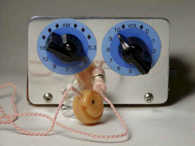
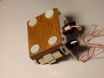
Here is a simple radio that was designed to minimize unusual parts; there isn't even a detector diode! The sensitivity isn't as high as the one-transistor reflex but the simplicity is attractive. Strong stations will provide plenty of volume into a crystal earphone or an external amplifier. The AM Loopstick was purchased on eBay but the enterprising experimenter can swipe one from the interior of a cheap radio. If the loopstick has more than one winding, use the one with the most turns. Wind 3 or 4 turns near one end of the winding as seen in the photo. The tuning capacitor in the prototype is from an old radio and the little plastic dial was cut down such that it just fit into the back of a black pointer knob. The fit was tight so no glue was needed. All of the sections of the capacitor were connected in parallel to get the most capacitance for this loopstick.
All the other parts are common. The transistors can be just about any small-signal type. The prototype uses the metal can 2N2222, primarily for looks. Some transistors may have too much high frequency gain; if the circuit squeals, try adding a small resistor in the emitter of the first transistor, maybe 47 ohms, the smaller the better as long as the circuit is stable. The large 47 uF could be smaller in most cases but the circuit can pick up hum if the wires are too long. Don't leave out the large capacitor across the battery, it provides needed low power supply impedance.
The circuit is built on a piece of 3.8" x 2.7" x 0.5" stained and varnished oak. The terminals are copper-plated nails used for weatherstripping. These nails are commonly available in home improvement stores and are also available in brass which is also solderable. Pre-drill the holes to make nailing easier and use a nail set or larger nail turned upside-down to make it easier to hit only the desired nail. The loopstick is held in position by an ordinary nylon cable clamp and the battery is mounted in a spring holder. The front panel is aluminum that was polished to a nice shine. First sand off all scratches with fine sandpaper. Then remove the sanding marks with ordinary kitchen steel wool. Now polish the surface with the finest steel wool in the paint department, usually "000". Then, for the real shine, polish the surface with a polishing compound like rouge. By the way, those paper-wrapped sticks of polishing compound are easily dissolved by lighter fluid (naphtha). Just put a few drops on a tissue and rub it on the end of the stick to load the tissue with compound. These polishing steps go quickly and you can have a mirror finish in a couple of minutes.
The front panel has a couple of scales for the tuning and volume printed on high gloss report cover stock and sprayed with a protective clear spray. The feet on the bottom are recessed in the oak using a forstner bit. The corners on the aluminum and oak were rounded on a belt sander.
When building crystal radios or other simple receivers, the experimenter often wonders about the relative performance of the different diodes in the junk box. Here are the results of several experiments using the typical types available to the hobbyist. The source is a low impedance and the load is a fairly high impedance. A particular diode will behave differently with different impedance levels but for low received signal levels these measurements are fairly predictive of the relative performance in most circuits. The diode types include germanium, silicon, Schottky, and even a light-emitting diode! The test setup uses an accurate RF synthesizer, a homemade AM pin diode modulator driven by an audio generator, a simple test fixture, a DC power supply for adding bias current, and a sensitive audio voltmeter. The setup shown below was used to test the diodes at several frequencies with a low modulation index (about 20%) and the near optimum bias current was determined by varying the DC supply.
Initially an RF level of about -15 dBm was used but this level was dropped to -25 dBm without much change in the relative results. The best performance was provided by an H-P (Agilent) diode, the 5082-2835 with a tiny 10 uA of DC bias. The -25 dBm (35 mV p-p) results are shown below using the 5082-2835 Schottky diode at 20 MHz as the 0 dB reference point. The dB numbers are the audio level at the audio meter for the different RF carrier frequencies. Some variability is due to the test setup.
| Diode Part Number | DC Bias | 20 MHz | 60 MHz | 100 MHz | 130 MHz | Notes |
| 5082-2835 Schottky | 10 uA | "0" dB | 0 dB | -2.5 dB | -4.5 dB | quite good! |
| 1N5711 Schottky | 10 uA | -0.5 dB | -0.5 dB | -2.0 dB | -3.5 dB | better at high freq. |
| 1N4454 silicon (similar to 1N914) |
20 uA | -8.5 dB | -9.5 dB | -10.5 dB | -11.5 dB | pretty bad! |
| 1N277 (Ge.) | None | -3.0 dB | -4.0 dB | -6.5 dB | -8.5 dB | not great at high freq. |
| 1N34A (Ge.) | None | -3.0 dB | -4.0 dB | -6.5 dB | -8.5 dB | . |
| 1N32 | 10 uA | -1.0 dB | -1.0 dB | -3.5 dB | -5.0 dB | microwave diode |
| Red LED | 10 uA | -4.0 dB | -4.5 dB | -8.0 dB | -11 dB | not bad for low freq. |
The Schottky diodes are the all-around winners if bias is used but they do not perform as well as a germanium diode without bias. Other small-signal Schottky diodes gave nearly the same results as the 1N5711. Other germanium diodes were tried but the results were nearly identical to those shown. (The 1N60 was not available for testing.) The 1N4454 is similar to other ordinary silicon diodes and the results were poor, as expected. Several LEDs were tried and a bright type red led gave fairly good results as shown. Zeners were tried with dismal results in both directions. Large rectifiers like the 1N4001 were similarly poor.
Misc.: