The reflex receiver uses the same transistors to amplify the RF and the audio independently, effectively doubling the transistor count! Reflex designs were born in an era when transistors cost several dollars each and pressing them into "double duty" was worth some effort. Tax laws categorizing radios with two or fewer transistors as "toys" added to the motivation. Today, excellent transistors can be had for a few pennies each, not to mention ICs filled with them and "Boys Radios" with only two transistors are collectibles! But it is still interesting to push for more performance from simple circuits and the reflex receiver is not disappointing.
| Wonderful One-Transistor Radio | |
| Two-Transistor Radio | |
| Matchbox Radio | |
| Computer Speaker Radio | |
| Older Designs |
This reflex radio project was inspired by Robert Bazian 's design. His reflex radio is the "darndest" thing I have seen and his spectacular results inspired me to come up with my own version. These designs are similar to two-transistor circuits used in some ancient Japanese "Boys Radios" except that the inter-stage transformer directly drives the speaker.
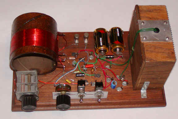
My version is restricted to components that are fairly easy to get or make and the results are amazing. Instead of a loopstick antenna, I use an air-wound coil that is easy to make and I use an ordinary "telecom" transformer for the feedback signal. (I have a plentiful supply of these, by the way.) The one part that might be a little hard to get is the MPS-A18 and I don't recommend substitutions unless you can find a very high gain transistor. A Darlington can be made to work but there may be noticeable distortion. Here is the schematic:
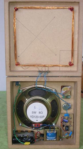
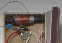
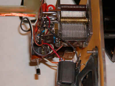
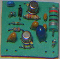
The antenna coil is just 20 turns wrapped around four insulated posts as seen in the photos and shown in the diagram below. I used nylon posts but ordinary bolts covered with tubing would work fine. The dimensions are not particularly critical; those shown happen to fit inside the case I chose. If your antenna tunes too low, remove a turn or two and if it only picks up stations at the top of the band, add a couple of turns. The signal is coupled to the receiver by two turns wrapped right on top of the 20 turns. This winding technique is simple but it has the drawback of having more than desirable capacitance and that limits the tuning range with a standard 365 pF variable capacitor. To get around this limitation, a switch and 100uH inductor has been added as a band switch to allow the reception of the higher frequency stations. This antenna system also tends to give more regeneration at the high end of the band and the volume control (5 k) must be turned down a bit.
This circuit would make a great single-station radio! Leave out the switch and inductor and replace the 365 pF variable with a fixed value selected to tune the desired station. You might want to add a shunt resistor or trimmer across the 5k pot to limit its resistance to the value that gives maximum volume without distortion.
The telecom transformer is designed for high bandwidth ISDN or T1 digital signals and it doesn't have much of a response to the audio signal. Other types should work, including some pulse transformers and other broadband RF transformers as long as they look like a low impedance to the audio. Try winding your own on a piece of ferrite and experiment with different turns ratios.
The detector diode is a Schottky type intended for RF applications but a germanium detector diode will also work. There is a bias current flowing so other types of diodes might be worth a try (see detector diodes). I may have to try an LED just because it is so odd.
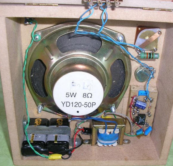
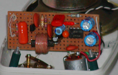
The output transformer may be a 1k to 8 ohm audio type or even a 12 volt filament power transformer. Some power transformers sound muffled due to poor frequency response so if your radio sounds like the treble control is all the way down, try changing to a different style of transformer. But don't hesitate to try a power transformer; the best performance I got was with a power transformer, outperforming my smaller 1k to 8 ohm audio type seen in the photos and they are easy to find. (The 12 volt winding goes to the speaker and the 120 volt winding goes to the transistor.) Although I didn't try it, a 6 volt power transformer might work well with a 4 ohm speaker.
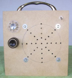
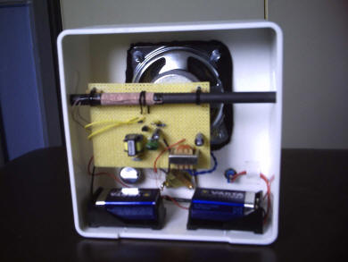
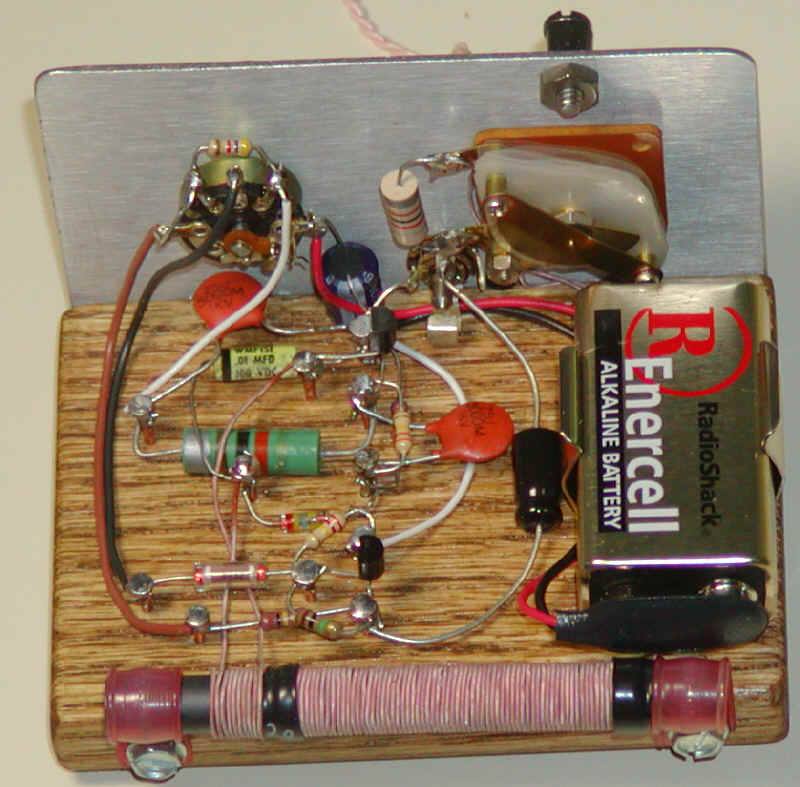
My radio is built into a phenolic box with a clear plastic lid. The legends were printed on colored paper and glued with spray adhesive to the inside surface of the plastic. A couple of terminal strips and the terminals of the speaker, switch and capacitor mount all of the parts. The center of the fiberglass antenna support was cut out to make room for the speaker magnet.
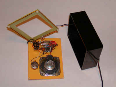
The black cord is from a 15 volt molded power supply that I used in place of batteries. If you don't like messing with batteries either, choose a supply near 18 volts.
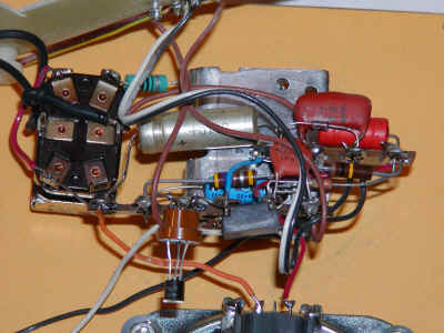
The transistor is in a socket to allow for easy experimentation and is optional. Except for the transistor, the component values and types are pretty forgiving so substitutions may work fine.
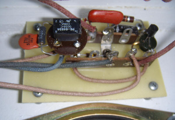
The audio transformer in these photos (fastened directly to the speaker) is a gray potted type that isn't very common but "regular" types will work just as well as will many 12 volt power transformers. Choose one near 1k to 8 ohms.
![]()
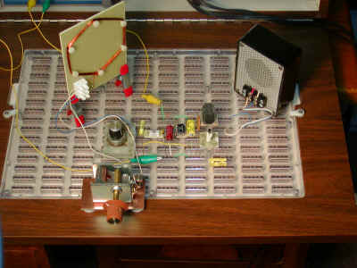
Don't feel compelled to copy the mechanical design exactly! It works just about any way it is made. Here is a photo of a nicely working version I tried on a prototyping system that I am making for my kids:
![]()
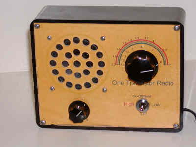
I constructed another version with an emphasis on volume:
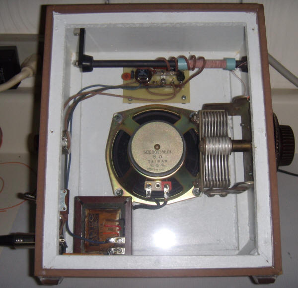
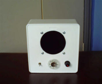
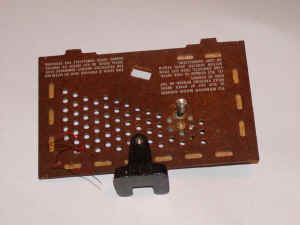
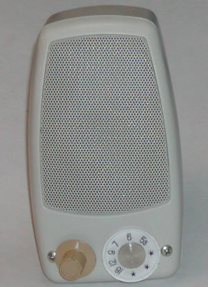
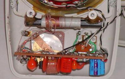
This version is built into an old speaker enclosure and the pressed board back is replaced with clear plastic to allow viewing the insides. One might be called upon to prove that there is only one transistor! From the front, the radio looks like an ordinary brown speaker with a tuning knob on one side and a volume control and power switch on the other. Power is supplied by a 24 volt molded power supply. The original speaker was replaced by a two-way radio replacement speaker that seems very efficient. The audio transformer is a 70 volt music distribution type wired for maximum step-down. The ferrite rod is 6.5" long, held at the ends by rubber feet, and is tuned by an old Atwater Kent variable capacitor. The pulse transformer is mounted on the base from a fluorescent lamp starter and the transistor is in a socket to help make those component's thin, short leads compatible with the clunky solder terminals. The secondary on the ferrite rod is a few turns of hookup wire wrapped loosely near one end of the primary. Playing with the spacing and position gave good performance over the whole band. The variable capacitor tunes the loopstick over the entire band without a band switch. This version is indeed loud and it's fun to show it to other hobbyists who actually appreciate it!
![]()
Here is a picture of a neat gadget you might like:
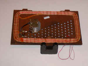
This device is a modified antenna from an old tube-type radio (commonly wound on the inside of the back cover). I added a tuning capacitor, a two-turn secondary and a heavy stand to hold it upright. The gadget makes playing with various designs a little easier. If you happen to have a loopstick antenna from an old radio, it will work quite well. Try more than two turns for the secondary, however.
For the advanced experimenter:
A second transistor audio amplifier driven by a 10k to 2k transformer would give incredible performance! | |||
A line-powered version using two high voltage transistors might be interesting, easily driving a larger speaker. | |||
A varactor tuned receiver might allow the regeneration to be adjusted automatically as the radio is tuned. The voltage that tunes the varactor could also adjust the gain in some way. | |||
|
Robert Bazian suggests using his circuit as a 455kHz IF amplifier in conjunction with another transistor as a traditional autodyne front-end. He claims that his prototype works about as well as a typical transistor radio!
Make sure to visit reader Mike's page, http://oldradiobuilder.com/One%20Transistor%20Radio.html (another website) to see a true work of art version of this radio! He also made some interesting improvements. Also see Tom's work of art with interesting improvements: http://www.tompolk.com/radios/macrohenrydyne/macrohenrydyne.html Make sure to see Don's page detailing his version.
Marcos from Brazil built this version:
Karen from the UK built this one:
Karen writes: The case is a CD storage box, bought from a UK supermarket. It was difficult to work and not really a good choice - the plastic is brittle and cracks easily. My radio uses a BC549C transistor. This has a lower typical beta than the MPS-A18 so if anyone is thinking of using this part they might like to buy a half dozen and try them to find the best. I suppose I got lucky - my only BC549C works about as well as an MPS-A18. I used a pulse transformer for the RF transformer. This has three windings, two of which I joined together to form the non-collector winding. I discovered the windings were all wound in the same direction, so to join two in series it was necessary to have a link that passed under the device (had I joined two adjacent pins the windings would have cancelled). The circuit is hanging on the loopstick, which is conveniently supported by two slots on the inside of the case! A rubber foot on the back of the speaker provides all the extra support needed. I didn't fit a back to my radio - how can you prove its a one transistor radio if you have a back on it? :) I had to lop about two centimetres off my loopstick to make it fit. This is always a fraught affair because ferrite is so very hard and brittle. There are diamond-tipped tools that will do the job but if, like me, all you have is a junior hacksaw then it can be accomplished by carefully cutting a groove all around the point you want to cut it. With a but of luck you can then cleanly break off the excess with a little force. But there is a lot of luck involved so don't attempt to cut down your loopstick unless you absolutely have to. My loopstick is held to the board - or more correctly, my board is held to the loopstick - by cable ties and cork stand-offs. DON'T do what I did many years ago and use wire loops to secure the loopstick. They represent shorted turns and will completely prevent your radio from working! I can get all three of our local MW stations on this radio, one at excessive volume. I should point out that I am less than thirty miles from our Droitwich transmitter, which doubtless helps. I found the circuit to be very well behaved and not at all critical in construction. UK hobbyists may be interested to know that most of the parts I used are obtainable from our Maplin chain of high street stores: | |||
| Part Maplin part number | |||
| BAT43 schottky diode VR19V | |||
| BC549C transistor QQ15R | |||
| Pulse transformer PT6 N79CC | |||
| Audio transformer LT700 LB14Q Maplin also do a loopstick that you could almost certainly use, though I haven't tried this - Maplin part number LB12N. The only part you can't get from Maplin is the tuning capacitor so you'll have to look to an alternative supplier for that. What an amazing circuit! It breaks all the rules. Is anyone up for the challenge of an FM version? :))
|
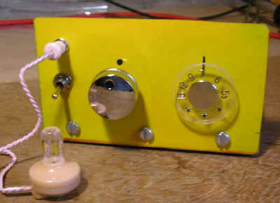
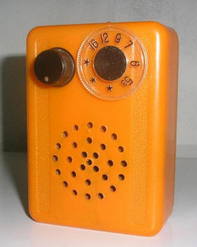
| Here is a two transistor radio that really performs! The first transistor acts as a reflex stage similar to the one-transistor reflex radio above except that no RF transformer is used. Instead, a 10 millihenry choke sends the RF to the diode detector and the audio to the output stage. This simpler approach is not as sensitive as the transformer feedback version but the addition of a simple one-transistor audio amplifier makes this receiver really scream. You will not be using this radio with the volume control turned up full! And you can really pull in stations with a simple loopstick antenna. | 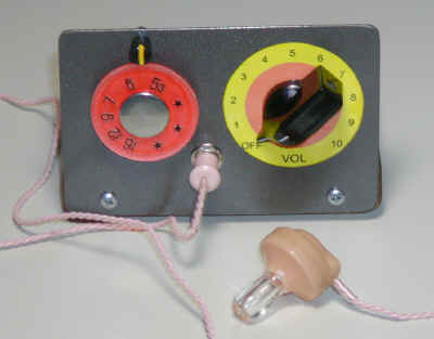 |
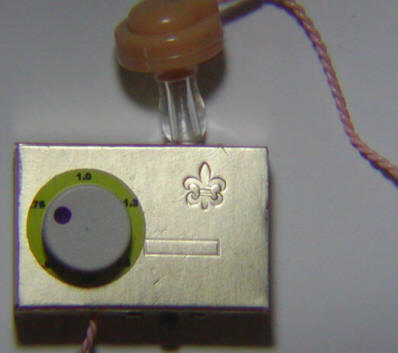
This time I painted the aluminum with a hammertone style paint. I glued a piece of orange paper on the backside of the tuning dial to make it easier to read and to improve its looks! The volume control dial is printed on a laser printer in complimentary colors. (It is actually more orange than the photo shows.) The tuning dial has a pointer made with a slotted screw and standoff. The screw and standoff are painted black and the slot is filled with yellow paint to make the pointer.
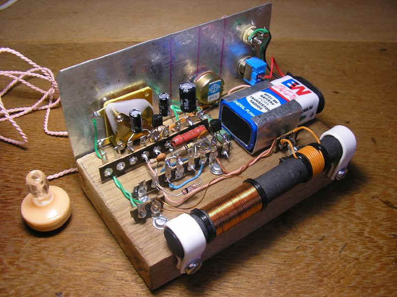
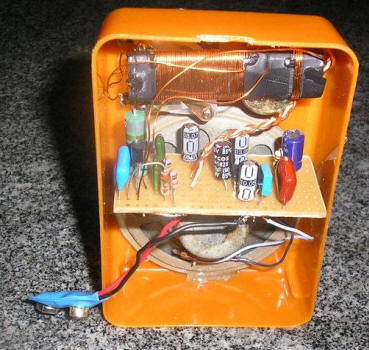
I did not have a 5 k potentiometer handy so I just paralleled a 500 k pot with a 4.7 k resistor which works fine due to the high input impedance of the audio stage. Also notice that I added a 1000 uH choke across the tuning capacitor to reduce the loopstick inductance a bit, instead of removing a few turns. The loopstick was too high in inductance for this capacitor but I didn't want to risk harming it. The wire is litz but ordinary enamel wire will also work. A small line of glue is on the bottom of the windings to help hold them in position. My secondary is more like 10 turns but the number isn't critical. I chose a germanium diode with nice colors for its looks instead of a drab schottky diode. (Great engineering, huh?) You may also notice that the input capacitor to the amplifier is a .47 uF ceramic and not a 1 uF electrolytic and the output capacitor is a 10 uF instead of a 1 uF but these values are not critical. The first stage has enough signal to power an earphone without amplification or the experienced experimenter can replace the second transistor stage with one capable of driving a speaker, perhaps a stage like the 2N2219A stage in the speaker version of the All Band Receiver.
|
Here is a tidy, attractive version using brown phenolic standoffs built by Marcos Kusnick from Brazil. Marcos says: Hello Charles. That’s the boy. As you said in your page it really performs! It is the best MW radio that I've made.
|
 |
![]()
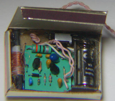
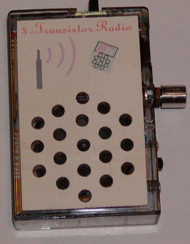
Building little radios into matchboxes is a traditional hobby pursuit and reader Augustin from Romania inspired me to try my hand at it. For my matchbox receiver, I chose my two-transistor reflex receiver with a couple of modifications:
The tuning capacitor is replaced with a varactor diode and potentiometer to save space and the antenna coil is a modified loopstick from an inexpensive AM radio. The circuit is powered by a tiny 10A type 9 volt battery which should last about 30 hours with the 1mA drain.
The first step was to choose a nice matchbox. After a trip to the local flea market, I had a jar of "collectible" matchboxes. My favorite is shown below, carefully taken apart and held flat by a plate of glass and then reassembled to form an easy to work in enclosure:
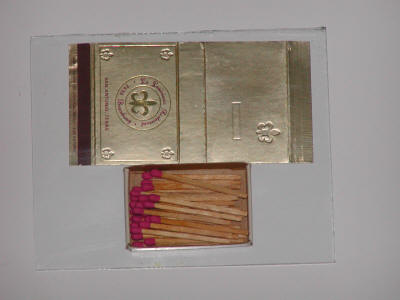
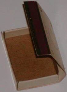
Alcohol removed the printing from one side of the box which became the front and the drawer section was glued into place forming the backside of the front of the radio. The new flap becomes the back access door and the striker fits inside the box to secure the flap. A slight taper and notches make this flap snap into position much like the lid of a raisin box.
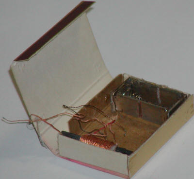
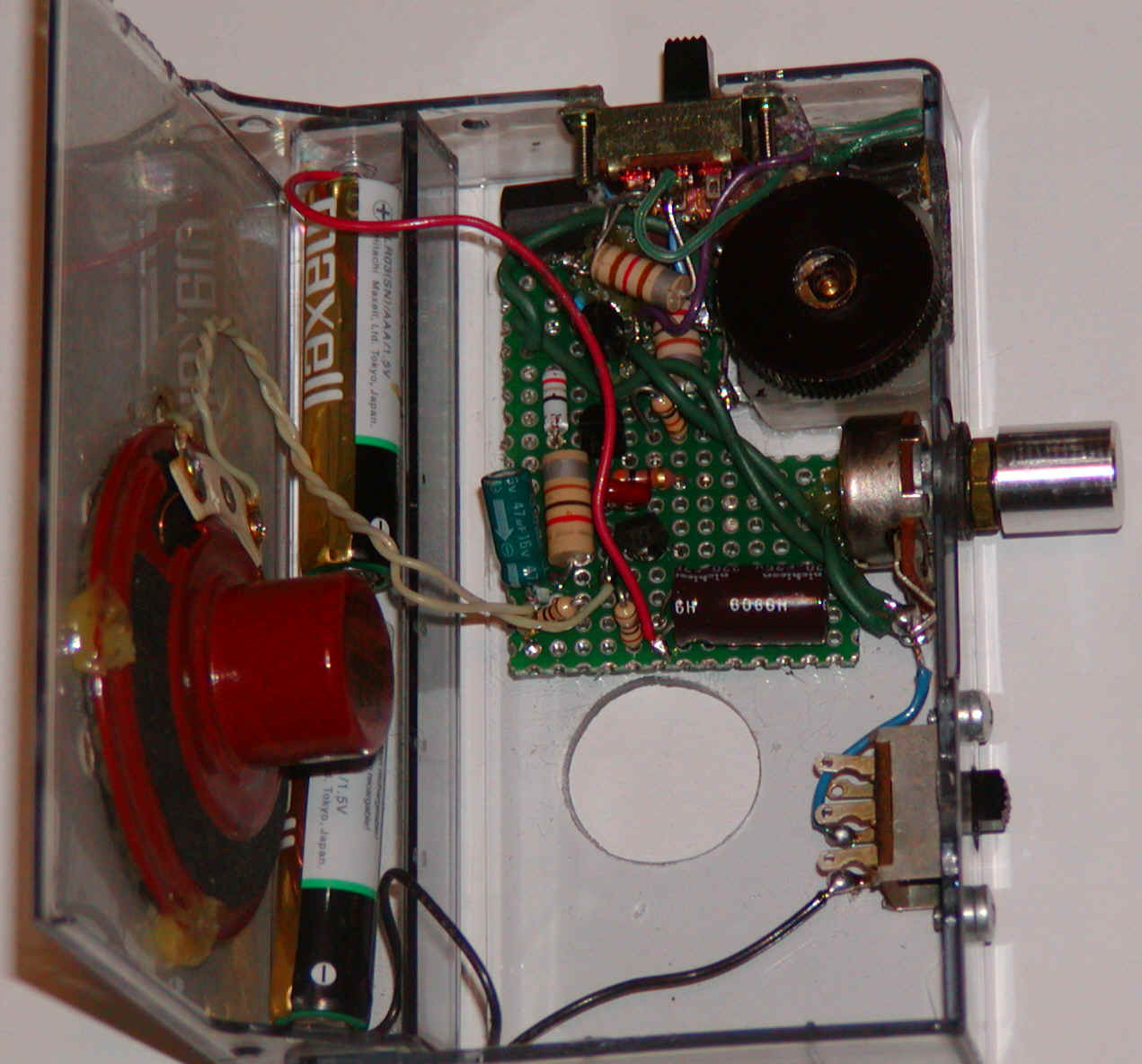
A battery compartment was fashioned from tinned PCB material and the battery springs from the sacrificed AM radio. Note that strips of copper were removed so that the holder would not short the battery.
Note to self: Don't choose a metal foil matchbox for a matchbox radio! The foil can short things out and tends to lower the Q of the antenna coil. Looks good, though. The tuning pot was mounted on the face of the box as shown in the photo. After losing a battery to premature discharge, the foil around the legs of the pot was trimmed away! The tiny loopstick antenna was glued into one end of the box and the electrical tuning components were mounted on a tiny piece of PCB material directly opposite the tuning potentiometer.
 |
|
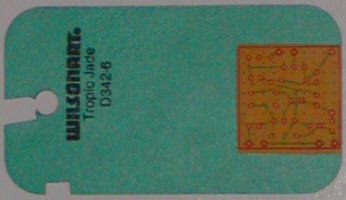
The circuit layout was done with the free layout software from ExpressPCB and a printout of the design was glued to a piece of "Tropic Jade" laminate for use as a drill guide.
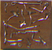
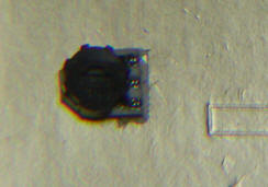
A dental pick was inserted into the holes for wires and component leads were bent around the pick to form eyelets. After a bit of a struggle, a power switch was added and the completed circuit was installed. The sharp observer will note the absence of the more attractive metal can transistors. I had stability problems due to too many turns on the original secondary that I mistakenly attributed to the transistors. If your radio squeals or seems unstable, reduce the 12 turns to maybe 8 or so. A dial fashioned from a plastic foot was glued to the top of the potentiometer, finishing the radio. The radio works quite well for its size, giving good volume for my favorite station; in some parts of the house it is loud enough to need a volume control. I still can't believe these regenerative reflex circuits!
![]()
 Here
is a version built into a surplus computer speaker using an LM386
audio amplifier IC. The circuit is built onto a little piece of
phenolic perfboard that is secured by wedging the edges of the
perfboard into a couple of bifurcated standoffs. The on-off switch
is part of the volume control which is mounted next to the tuning
capacitor. The loopstick antenna is glued to a couple of plastic
posts that are part of the enclosure as can be seen in the photo.
The 9 volt battery is located in the C-cell battery compartment with
plenty of room to spare. The performance of this simple
receiver is quite good, giving a blasting full volume on a couple of
stations with no antenna. Play with the number of turns on the
secondary to get the best results; more turns will give more
sensitivity but the circuit might become unstable, especially at the
low end of the band. Fewer turns will give better sound but at some
point the sensitivity will drop off. Three turns makes for a great
receiver with my version. I had to remove a significant number of
turns from the loopstick to make it tune properly with the 365 pF
variable capacitor I chose because the loopstick was designed for a
significantly lower value capacitor. Here
is a version built into a surplus computer speaker using an LM386
audio amplifier IC. The circuit is built onto a little piece of
phenolic perfboard that is secured by wedging the edges of the
perfboard into a couple of bifurcated standoffs. The on-off switch
is part of the volume control which is mounted next to the tuning
capacitor. The loopstick antenna is glued to a couple of plastic
posts that are part of the enclosure as can be seen in the photo.
The 9 volt battery is located in the C-cell battery compartment with
plenty of room to spare. The performance of this simple
receiver is quite good, giving a blasting full volume on a couple of
stations with no antenna. Play with the number of turns on the
secondary to get the best results; more turns will give more
sensitivity but the circuit might become unstable, especially at the
low end of the band. Fewer turns will give better sound but at some
point the sensitivity will drop off. Three turns makes for a great
receiver with my version. I had to remove a significant number of
turns from the loopstick to make it tune properly with the 365 pF
variable capacitor I chose because the loopstick was designed for a
significantly lower value capacitor. |
Marcos from Brazil built this version into a soap box:
You can just see the LM386 hiding behind the electrolytic.
![]()
The following circuits are included to give the experimenter ideas but they don't perform as well as the radios above. The reflex radio will work with lower battery voltage but there will be less regeneration in the RF stage and more stages are needed to get enough volume to drive a speaker.
One of the more elegant configurations is shown below; I could not identify the original inventor but he deserves recognition! I have made a couple of modifications to the original circuit for better performance with today's superior transistors. In fact, with the 2N4401 the circuit will exhibit some regeneration with the pot set near a low value so this circuit could be considered to be a "regenerative - reflex" receiver.
Here is how it works: The RF is picked up by a large coil or loopstick tuned with an ordinary variable capacitor and is amplified by the first transistor. (A short antenna may be added for weaker signals.) The gain of this first stage is controlled by the 1k pot in the emitter which also serves as the volume control. The original designs with germanium transistors simply grounded the emitter due to the lower available gain. The second transistor acts like an emitter-follower at the RF frequency providing a low impedance RF source for the detector diode. The detected audio appears at the bottom of the tuned circuit across the 10 nF capacitor and, since the coil looks like a short at audio, also at the base of the first transistor. The audio is amplified by the first transistor in the same manner that it amplified the RF. The second transistor now acts like a common-emitter amplifier for the audio because the 1 mH choke and 22uF capacitor look like a short to ground at audio frequency. The bias for both stages is also provided by feedback via the diode; there are no bias resistors - really clever!
This two-transistor version won't knock you socks off with volume but it can provide useable volume into a high impedance dynamic earphone or headphone for the stronger stations. The 1000 ohm earphone may be replaced with a 1000 ohm to 8 ohm transformer for driving low impedance earphones or speakers. You will need to hold the speaker up to your ear, however! Feel free to add an audio amplifier!
The coil indicated in the schematic is wound on a 3.25" cardboard tube but other diameters will work, too; the bigger the better. A ferrite antenna from a miniature transistor radio will also work and you can "play tricks" to get the required inductance. For example, in the three-transistor schematic an additional 100mH inductor may be switched in to lower the inductance to allow the reception of higher frequency stations. You could avoid adding this choke by switching the 365 pF capacitor to a lower tap leaving the end of the coil unconnected. In the little pocket radio the ferrite antenna coil and tiny capacitor needed a 120 mH inductor in series with the bottom of the coil to tune in the lower frequency stations. A switch was added to short this inductor for receiving the higher frequencies. (You can just make out the end of the ferrite rod above the circuit board to the left of the switch and the 120 mH molded choke directly below the switch.) Play around with different coils and tap positions - the circuit is pretty forgiving and you might find a superior configuration. The advanced experimenter might increase the power supply voltage significantly, use a much larger coil, and use an efficient transformer-coupled speaker to see how much performance can be had from only two transistors. By the way, years ago I had a tiny green two-transistor radio that used a very similar circuit! It wasn't much more than an inch wide and, although it had what looked like a speaker grill, it used an earphone only. And, it didn't work any better than this circuit, either.
The photos below show two versions of a three-transistor version; the third transistor really makes the receiver come alive. In fact, the breadboard version is entertaining me with the "Clark Howard" show from across the room as I type. It works quite well without an antenna on the stronger stations. In order to avoid an audio transformer I connected two 16 ohm speakers in series and mounted them side-by-side in a wooden box. Keep the "phasing" of the two speakers the same by connecting the left terminal of one to the right terminal of the other (assuming they are identical speakers). The pocket radio version uses a tiny 39 ohm speaker I happened to have. Don't be misled; the "pocket radio" version really doesn't work all that well due to the small ferrite antenna coil, small speaker and low battery voltage. But it does work! It would serve better as an "earphone only" design.
Note: this older design pictured above works much better with a 4.5 volt battery and with the first tap at only one or two turns instead of nine turns. Mine now tunes the whole band without the band switch and with better selectivity, thanks to the one turn tap. Mine doesn't have the antenna connection and it simply uses the coil to pick up the signal. I also removed a few turns to reach the top of the band (now 43 turns).
The 1mH in the collector of the first transistor is optional in both circuits; it gives a little more RF gain. The taps indicated may be changed but taps more near the top of the coil will increase the regeneration and reduce the selectivity. Experimentation is recommended! The transistors are not critical but use reasonably fast "general purpose" types. The 2N3904 and 2N3906 are good alternatives. The detector diode may be a 1N60, 1N34, 1N270 or other small-signal germanium type. Most of the values are not particularly critical so small changes should be fine. (The 300 ohm could be a 270 to 390 ohm, for example.) For the advanced experimenter: These circuits are operating on 3 volts but a much higher voltage supply will give much more gain, especially the speaker driver and a larger coil will give more sensitivity.
![]()
reflex radio, reflex receiver