![]()
(also see the CD4069 Version)
Pretty ambitious title, wouldn't you say? Well, follow the reasoning: If you lower the voltage on the two-transistor flasher to 1.5 volts, the loop gain drops too low for sustained flashing. (See the circuit below.) But, the circuit is highly regenerative and only needs a very tiny push to get it going. By adding a short wire, only a few inches, to the PNP base, the circuit will be triggered into oscillation by the AC electric field from the electrical power (50 or 60 Hz in most places). If the resistor and capacitor timing values are selected for oscillation near the line frequency, the circuit will flash at that rate in perfect synchrony. Now the "Atomic Frequency Standard" part: The line frequency is only fairly accurate at any given instant - perhaps within a few hundred PPM - but the long term error is kept very low by comparing the frequency with national time standards which are, of course, based on an array of atomic standards! So, if you rip the oscillator out of a battery-powered wall clock and replace it with this circuit, the clock will exhibit little or no long-term error. Most wall clock oscillators generate pulses at one or two hertz to drive a little solenoid and this circuit may be adjusted to run at this lower frequency by increasing the timing resistor. The low frequency oscillations will be synchronized to the line frequency. Adjustment can be tricky and should be done with the circuit installed in its final location. The circuit will have a tendency to jump to different divide ratios if it isn't adjusted perfectly. Once it is running, nothing can be changed, including the antenna length or the circuit will jump divisors. (Divide by 59 instead of 60, for example.) It would be more reliable to add a CMOS frequency divider chip to get the lower frequency but an experienced hobbyist can make it work and it is pretty fun to play with. Adjusting the circuit to produce the line frequency without division is much less critical and more forgiving of antenna changes, etc. The circuit can even be used to generate odd-order multiples of the line frequency but the adjustment is quite sensitive.
|
Approximate R Values:500k for 1 PPS28k for 10 PPS4k for 60 PPSUse a potentiometer for |
The circuit shown uses a 4 uF film capacitor but other values will work if the timing resistor is changed in inverse proportion. For example, a 1 uF capacitor would require a resistor about 4 times larger. If you wish to simulate this circuit with a Spice program, connect a 50 or 60 Hz voltage source set to about 100mv, a 100 megohm resistor and a 100 pF capacitor all in series between ground and the base of the PNP to simulate the electric field. For "real-world" testing, a period counter is hard to beat but an oscilloscope with line trigger will also do the trick.
An optional booster circuit is shown if high current pulses are required as when driving a solenoid. If the pulse is too short, add a 10k resistor in the base of the NPN. Some frequency retrimming will be required.
![]()
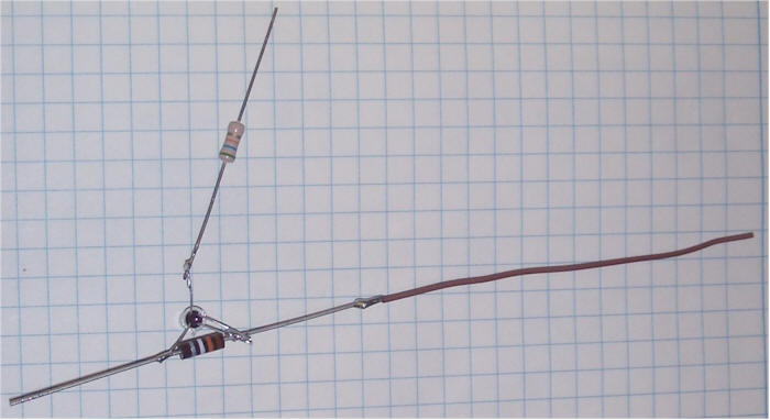
A reader asked if there were another way to receive the line frequency for clocking a little microprocessor. I decided to try an extremely high impedance buffer amplifier employing an unusually high value resistor and an electrometer JFET:
An ordinary neon lamp, like the NE-2, may substitute for the 13 gigohm resistor. They contain a tiny bit of radioactive material that makes the neon slightly conductive.
The drain resistor is selected to give about 2.5 to 3 volts on the drain with no antenna connected and the value will depend on the characteristics of the particular FET. My FET needed about 68k. Too low a value and the output waveform will be too positive and too high a value and the waveform will not reach 5 volts.
The antenna is a length of insulated wire about 5 inches long (13 cm). The length isn't critical but a longer wire will give a bigger signal, if necessary. Power connects to the top of the vertical resistor, the signal is taken off the bottom of that resistor, and the left side of the bottom resistor is ground.
The case and gate of this metal can FET are connected together, but most electrometer JFETs are in the three lead TO92 package.
The waveform is huge when holding the circuit above the workbench:
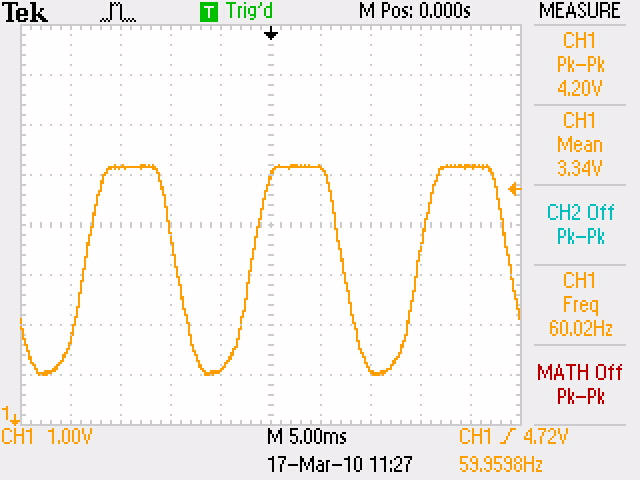
This waveform should be fine for feeding directly into a high impedance microprocessor input. Zero volts is at the bottom of the screen, so the waveform reaches about 1 volt and the top of the waveform clips just above 5 volts, where the power supply was set. This signal could drive a single CMOS gate to produce a low impedance square wave. The circuit works fine with a lower value resistor, but the smaller the resistor, the longer the antenna needs to be to achieve the same signal size. A neon lamp in place of the gate resistor works great.
Also see the CMOS version.