
![]()
|
Experimenter's Ionization Chamber for quick, simple experiments. | |
|
Improved Transistor Circuit drifts much less than the single Darlington transistor circuit. | |
|
The Polonium Pen for spotting those "hot" drinks. | |
|
Nuclear War Detector - save yourself a trip to the window. | |
|
Frankenstein's Dosimeter uses parts from a CDV715. | |
|
Radon Accessory for any radiation detector. | |
|
Components Discussion for the scrounger | |
Other pages of interest:
|
Ionization Chambers (page 2) featuring high-value resistors as feedback elements. | |
|
Prophylactic Effect of Second Hand Smoke - possibly? | |
|
Radon Detector for the Student includes a simple ionization chamber. | |
|
PicAXE Ionization Chamber needs no special resistor. | |
|
Prospector's Ionization Chamber (Area 50) simulates a Geiger counter with an ion chamber. | |
|
Geopodium discussion area. |
When ionizing radiation (far ultra-violet light, x-rays, alpha and beta particles, etc.) pass through a gas, collisions with the gas molecules produces ion pairs, typically charged molecules and free electrons. If an electric field is present, the ions will move apart, each moving in opposite directions along the electric field lines until they encounter the conductors that are producing the electric field.
An ion chamber is an extremely simple device that uses this principle to detect ionizing radiation. The basic chamber is simply a conducting can, usually metal, with a wire electrode at the center, well insulated from the chamber walls. The chamber is most commonly filled with ordinary dry air but other gasses like carbon dioxide or pressurized air can give greater sensitivity. A DC voltage is applied between the outer can and the center electrode to create an electric field that sweeps the ions to the oppositely charged electrodes. Typically, the outer can has most of the potential with respect to ground so that the circuitry is near ground potential. The center wire is held near zero volts and the resulting current in the center wire is measured.
The voltage required to sweep the ions to the conductors before a significant number of them recombine or stick to a neutral molecule is usually under 100 volts and is often just a few volts depending on the dimensions of the chamber. The resulting current is extremely low and detecting individual particles is difficult, especially with ordinary air at atmospheric pressure. The simple chambers to be discussed respond primarily to beta particles and, if they can get inside, alpha particles. Most other rays don't cause enough ionization to be easily detected. These room-pressure chambers respond to the average level of ionizing radiation and do not provide "clicks" like a Geiger counter tube.
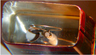
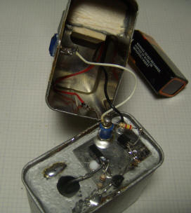
Here is a truly simple experimenter's chamber made from an ordinary cookie tin:
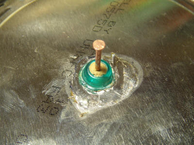
This experimenter's chamber is made from a 4" (10 cm) diameter, 5.5" (14 cm) tall tin with a tight-fitting lid. A 5-way binding post is mounted in the center of the can and a 4" (10 cm) wire is suspended from the post inside the can. The wire length is short enough to insure that it doesn't touch the lid. Another all-metal binding post and pin are installed in the bottom of the can, and a sheet of gray insulating plastic is glued into place to keep hastily constructed experiments from contacting the can. The electrometer circuitry will be extremely sensitive to stray electric fields, so a shield is mandatory. Another can previously containing mints is pressed into service:
It is important to shield the electronics! Please believe that; if you leave the electronics exposed you will not get good results.
A pin jack is soldered to the tin so that it can be plugged onto the pin on the chamber, and tape is applied to the lip of the can so that the pin is the only connection point. The inside surfaces of the shield are also insulated with tape to prevent accidental contact with the circuitry. The method of connecting the shield to the chamber can isn't critical and a clip lead will also work; the main culprits are the ever-present, low frequency, line-related electric field and changing electrostatic fields due to movement near the chamber. The wires from the circuitry can simply slip between the shield and the chamber, or a small notch may be made in the shield to make a little room for a few conductors. The opening of the chamber may be covered by the original lid, aluminum foil, or wire screen, depending on the experiment. Leaving the end open will let in too much stray electric field in most environments.
Here's a simple starter experiment:
The can is connected to the positive battery voltage through a 4.7k resistor, and the meter is connected between the collector of the transistor and the positive terminal of the battery. The meter is on the 1 volt scale for most measurements.
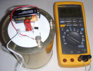
The transistor is an ordinary NPN Darlington type like the MPSAW45A. The resistor can be any value above 1k; it simply limits current in the event of a short circuit. A little piece of double-sided foam sticky tape holds the battery in position.
When an alpha or beta particle passes through the chamber, several atoms are ionized and the positive voltage on the can attracts the electrons. The positively charged atoms wander to the more negative center wire and, upon contact, reclaim their missing electrons. This process results in a current flow in the base of the transistor which is amplified by a factor near 30,000. This higher current flows through the 10 megohm resistance of the meter, producing the indicated voltage. As a point of reference, a reading of 10 mV would correspond to roughly 200,000 electrons per second, so even weak radioactive sources produce large numbers of ions.
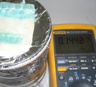
To observe the background and leakage level, the lid is placed on the bottom, the top shield is added and the reading is allowed several minutes to stabilize. The meter settles to a little over 30 mV and exhibits an occasional jump. A camping lantern mantle known to contain radioactive thorium is place in the lid of the chamber, and the lid is secured on the open end of the can such that the mantle is inside the chamber. The meter reading climbs to over 600 mV:
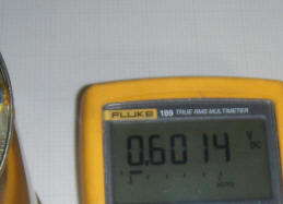
Placing the item to be tested inside the chamber in this manner gives the ultimate sensitivity, but care must be taken to avoid touching the center wire.
![]()
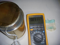
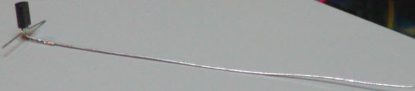
This very simple detector demonstrates how easily an effective radiation sensor may be made with a minimum of effort. Below is another way to build this simple circuit with even less effort. First, solder the 4" wire directly onto the base of the transistor:
 Drill a hole in the can right in the center of the bottom and epoxy the
transistor, face-down, such that the wire protrudes into the can without
touching the sides. Make sure that no epoxy touches the center lead of the
transistor (base lead). The epoxy is too conductive!
Drill a hole in the can right in the center of the bottom and epoxy the
transistor, face-down, such that the wire protrudes into the can without
touching the sides. Make sure that no epoxy touches the center lead of the
transistor (base lead). The epoxy is too conductive!
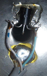
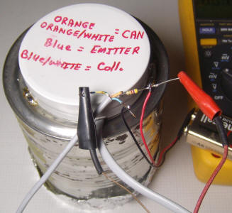
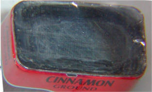
Connect two wires to the collector and emitter leads. The picture shows a length of solid copper telephone cable used for the connections. The two blue conductors are connected to the transistor legs and the two orange wires are connected to the can. The blue wires are given a little slack so that the cable pulls on the can connection and not on the transistor legs.
The resistor is connected on the other end of the orange wires. A mint tin is tacked to the coffee can in a couple of places to act as a shield and a wiring reminder is written on the back of the mint tin. A little optional notch is seen near the bottom of the mint tin that allows the phone cable to exit the tin without being pinched. The opening of the coffee can is covered with ordinary kitchen aluminum foil held in place by an elastic band.
Without a radioactive source, the meter reading settles to 50 mV and placing the lantern mantle on the foil gives a reading of just under 150 mV. The reading is lower because the foil is blocking a significant amount of the radiation from the mantle.
This simple circuit has serious limitations. It is extremely sensitive to the ambient temperature and a slight warming will cause a large increase in the zero reading and the gain. A modern small-signal transistor should be chosen since older or larger die transistors will probably exhibit too much leakage current. Despite these limitations, the simple circuit can be used for sensing unusually high radiation levels, observing sudden changes as when bringing a radioactive item near the chamber window.
![]()
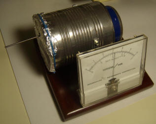
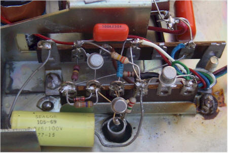
The single Darlington circuit could use more gain for detecting weaker sources, but simply adding another transistor exacerbates the temperature drift problem. By building a differential amplifier with one side not connected, a temperature-compensated circuit results:
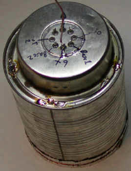
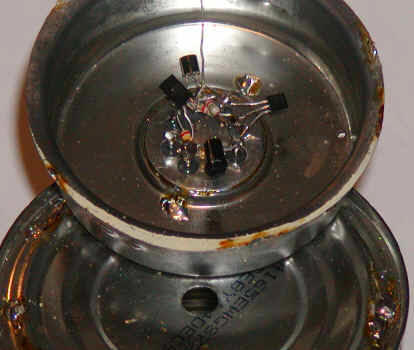
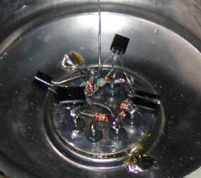
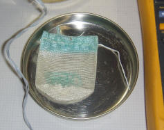
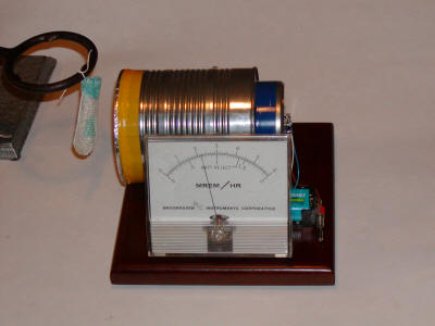
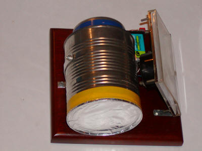
If the room temperature increases a little, both sides leak more current but the voltage across the meter stays about the same. The 10k resistors are not necessary but are included to protect the transistors from inadvertent shorts during testing. Another 10k resistor between the battery voltage and the outer can is probably a good idea in the event the can is shorted to the base of the transistor. The schematic shows 12 volts but a 9 volt battery works fairly well. The higher voltage sweeps the ions out of the chamber faster, before they have a chance to recombine so the meter reading will be a little higher at 12 volts. The sensitivity is good; the photo shows the response to a radioactive mantle held about an inch away from an aluminum foil window on the end of the chamber. Construction of the chamber is similar to the earlier devices except the metal end cap from a spool of resistors is used for the shield. This end cap accommodates a multi-pin header that is used to hold the components and also acts as a feedthru. The ion chamber sense wire is soldered directly onto the base of the transistor and is suspended in air by the transistor without additional support. It might be a good idea to use a plastic bead to hold the wire more securely but this unit is well-behaved as-is. The meter should read upscale slightly but, if it doesn't, try connecting the sense wire to the other base and reverse the meter leads. If it still doesn't read a little above zero, clean the transistors with acetone. If that doesn't work, try new Darlington transistors since you probably have a leaky one. Hold a radiation source near the aluminum foil window and the reading should quickly climb. The meter can be a 1 volt digital panel meter or even a digital multimeter set to the 1 volt scale.
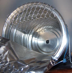
Since the original construction of this meter, a couple of useful modifications have been made. A wire shelf was added to allow items to be inserted into the chamber through a small hole in the foil without fear the item will touch the center pin. (The foil is peeled back to reveal the shelf in the photo to the left.) Later I realized it's better to put the "shelf" at the bottom so that the inserted item rests on the can with the screen simply acting as an electrostatic shield and physical guard.
Additionally, a 100k potentiometer was connected across the battery and the wiper was connected through a 1 megohm resistor to the base of the Darlington that was originally not connected. This potentiometer becomes an effective zero control. The picture to the right shows the reading produced by a 2% thoriated tungsten welding rod inserted into the chamber. The meter was zeroed with the new potentiometer before inserting the rod. The reading climbs quickly to over half-scale and drops slowly back to zero when the rod is removed.
Before leaving the darlington transistor approach behind, here are a couple of projects purely for entertainment value:
![]()
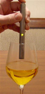
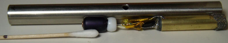
Recent events point to the need for a simple device for testing cocktails and beers for excessive quantities of polonium. The Polonium Pen is a pocket-sized ion chamber with LED readout that is perfect for the job. Simply hold the Polonium Pen over your drink and, if the LED lights up, order something else.
The circuit is similar to the single transistor detectors above and only requires two Darlington transistors, an LED, and one or two resistors along with a battery, power switch and tiny homemade ionization chamber. This prototype was a bit difficult to build, but the pen may be built in any number of ways as long as a couple of critical requirements are met. The wire probe sticking into the ion chamber must not touch anything that is ever-so-slightly conductive, not even most glasses, and the electronics must be surrounded by a metal package to shield it from stray electric fields. Because the ion chamber is so small, the LED will only light in the presence of a significant amount of radiation, most likely alpha particles.
The prototype will light up brightly when held near the Americium bit in a smoke detector's ion chamber and a polonium-laced drink should produce the same reaction. But most radioactive sources the experimenter is likely to have will not produce any response at all, placing this in the novelty category for most of us. The LED also comes on when the button is first pressed for a couple of seconds before fading out, hence the lit LED in the photo! This "feature" insures that the pen is working properly.
 The
first prototype required a high-value resistor (66 megohms) across the
emitter-base of the PNP darlington to get the LED to go out but the second unit
didn't need one, possibly due to superior insulation of the sensor wire. A value
as low as 22 megohm is fine and even lower is probably OK for
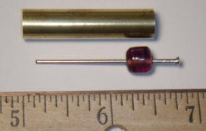
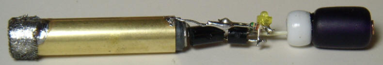
detecting really "hot" drinks! The prototype's ion chamber is made from a 1.5"
long piece of 11/32" dia. brass tubing and any similar size will work. The first
probe wire was a pin from one of those "pin art" bed-of-nails toys. The
insulator in the photo is a glass necklace
The
first prototype required a high-value resistor (66 megohms) across the
emitter-base of the PNP darlington to get the LED to go out but the second unit
didn't need one, possibly due to superior insulation of the sensor wire. A value
as low as 22 megohm is fine and even lower is probably OK for
detecting really "hot" drinks! The prototype's ion chamber is made from a 1.5"
long piece of 11/32" dia. brass tubing and any similar size will work. The first
probe wire was a pin from one of those "pin art" bed-of-nails toys. The
insulator in the photo is a glass necklace bead, but it turned out to be far too
conductive. It was replaced with a similar sized plastic bead. The new bead was
slightly too large for the brass tube, but by heating the tube with a soldering
iron while pressing the bead into the tube, the bead was easily cut down to
size. (Place masking tape on your fingers to prevent burns!) The bead was easily
popped back out with a screwdriver. A nail was glued into the bead with a little
length at the head end for making the transistor connection and then the
bead was glued into the brass tube. Another bead was temporarily slipped into
the other end to hold the nail in the center of the tube while the glue dried. I
switched to a nail for the probe because it fit in the new plastic bead better.
Tin and clean the nail before inserting in the bead, especially if steel flux is
needed. Later, solder the base lead on quickly; the plastic beads melt easily.
The epoxy technique mentioned earlier will also work well.
bead, but it turned out to be far too
conductive. It was replaced with a similar sized plastic bead. The new bead was
slightly too large for the brass tube, but by heating the tube with a soldering
iron while pressing the bead into the tube, the bead was easily cut down to
size. (Place masking tape on your fingers to prevent burns!) The bead was easily
popped back out with a screwdriver. A nail was glued into the bead with a little
length at the head end for making the transistor connection and then the
bead was glued into the brass tube. Another bead was temporarily slipped into
the other end to hold the nail in the center of the tube while the glue dried. I
switched to a nail for the probe because it fit in the new plastic bead better.
Tin and clean the nail before inserting in the bead, especially if steel flux is
needed. Later, solder the base lead on quickly; the plastic beads melt easily.
The epoxy technique mentioned earlier will also work well.
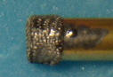 A
fine mesh screen was wrapped over the open end of the chamber to keep out wind
currents and electric fields. Rolling the screen between the fingers makes it
conform to the shape of the tube nicely. Solder the screen to the tube in one
spot. Some screen materials may require steel flux, but the screen should be
tinned with the flux and then washed with hot water and detergent before placing
it on the tube; that flux is highly corrosive! Copper screen is recommended; the
screen shown is plated copper and it takes solder nicely. Make sure the sensor
wire doesn't touch the screen and is fairly well centered in the tube (not
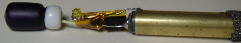
critical). The circuitry was constructed using point-to-point wiring and is held
in place by the base wire soldered to the nail's head and the emitter of the PNP
soldered to the brass tube. One end of a battery connector was fashioned
from another glass bead (long, dark tube on the right in the photo below) and a copper-plated
nail. A white plastic bead was used to cover the end of the copper nail where
the wire connects.
A
fine mesh screen was wrapped over the open end of the chamber to keep out wind
currents and electric fields. Rolling the screen between the fingers makes it
conform to the shape of the tube nicely. Solder the screen to the tube in one
spot. Some screen materials may require steel flux, but the screen should be
tinned with the flux and then washed with hot water and detergent before placing
it on the tube; that flux is highly corrosive! Copper screen is recommended; the
screen shown is plated copper and it takes solder nicely. Make sure the sensor
wire doesn't touch the screen and is fairly well centered in the tube (not
critical). The circuitry was constructed using point-to-point wiring and is held
in place by the base wire soldered to the nail's head and the emitter of the PNP
soldered to the brass tube. One end of a battery connector was fashioned
from another glass bead (long, dark tube on the right in the photo below) and a copper-plated
nail. A white plastic bead was used to cover the end of the copper nail where
the wire connects.
Some thin Kapton tape was carefully added to insulate the circuit from the outer tube but no tape was allowed to touch the NPN's base lead. Even electrical tape is too conductive!
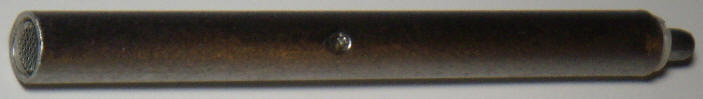
The outer tube was fashioned from 1/2" stainless steel tube, but copper would have been much easier to machine. The assembly was placed next to the tube to locate the hole for the LED, and a cotton swab was marked for depth with a black marker for applying epoxy to the inside of the tube to hold the glass bead battery terminal.
The swab was dipped in epoxy, inserted up to the black mark, and the epoxy was swabbed along the inside wall of the outer tube. After the epoxy was applied to the inside of the steel case, the assembly was slid into place (bead first) and the LED was positioned to face out the hole. After the epoxy set, conductive silver paint was gingerly applied to the edges of the screen to hold the ion chamber in position and to ensure a good electrical connection to the outer tube.
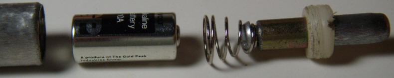
The other battery contact was made from a spring stolen from a AA cell battery holder fastened to a 1" steel standoff. The screw fits inside the spring and holds the narrow end of the spring to the standoff. The wide end of the spring friction fits in the steel tube to make contact. It is nicely centered by the tight fit and doesn't touch the center contact of the battery. When the button is pressed, the head of the screw makes contact with the battery's positive terminal, completing the circuit. The standoff "button" is held in place by a homemade nylon bushing that screws into the steel tube. (Threading the stainless steel was difficult! And fashioning the bushing from a nylon rod was no picnic.) The end of the standoff that protrudes was ground down to match the steel case after cutting off enough to eliminate the threaded hole. The steel case was given a coarse sanded finish, too, to hide all the scratch marks from the threading process! The brushed finish actually looks nicer than the original shiny finish and it hides fingerprints. This isn't the easy way to build such a pen but it gets the idea across.
A tiny 10A 9 volt alkaline battery was installed and the threaded nylon bushing was tightened. A little clear epoxy fills the LED hole and the pen is complete:
Every spy and "diplomat" should have one!
Note: It has been suggested that this pen might not detect polonium in a drink at concentrations that are lethal. Polonium emits copious quantities of alpha particles, really a mind-bending amount, but alphas cannot travel through a liquid. They barely make it through a few inches of air. So, the pen will only receive alphas from the very surface of the liquid. Polonium is ridiculously toxic and it doesn't take much to kill. On the other hand, polonium really pours out alphas. Bottom line is I don't really know if it works and I'm fresh out of polonium to try.
![]()
 Being
caught off guard by a nuclear war can be inconvenient. This project should alert
the utterly unobservant individual to any significant nuclear exchange or
radiation spill in the immediate vicinity, giving the owner time to kiss various
body parts goodbye. The detector consists of a small ionization chamber as
described above with the single Darlington transistor amplifier and a sensitive
level detector that activates a flashing LED when the chamber current reaches a
sufficient level.
Being
caught off guard by a nuclear war can be inconvenient. This project should alert
the utterly unobservant individual to any significant nuclear exchange or
radiation spill in the immediate vicinity, giving the owner time to kiss various
body parts goodbye. The detector consists of a small ionization chamber as
described above with the single Darlington transistor amplifier and a sensitive
level detector that activates a flashing LED when the chamber current reaches a
sufficient level.
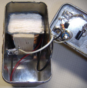
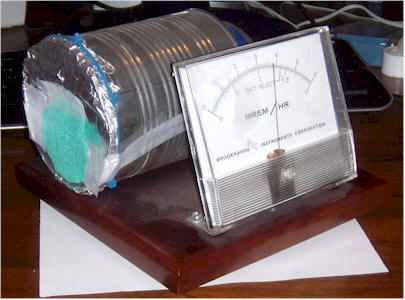
The device is built into two empty spice cans, one serving as the ion chamber and one as the circuitry shield and battery case. The sensitivity is set so that the lamp will begin to flash with approximately 3 pA of chamber current, about the amount one might expect if two lantern mantles were stuffed into the can. The mantles would be providing mostly alpha radiation in close proximity to the sense wire but in a nuclear exchange, the chamber would be responding to beta particles and gamma rays. The volume of the ion chamber is about 1/8 that of an old CDV-715 survey meter and there are no elements within the chamber to flatten the response for different energy particles. A wild guess for the sensitivity is between 2 r/hr and 10 r/hr for lamp flashing. In other words, the lamp will start flashing when the old CDV-715 is reading on the second or third scale. Suffice it to say, a blinking light isn't a good situation.
The schematic features a front-end like the experimental chamber above but without the current-limiting resistor connecting the can. It should be a less likely to accidentally touch the base of the transistor to the can since the unit is sealed and connecting the can directly to the battery makes wiring the rest of the circuit a bit simpler. A 1 megohm resistor can be used in place of the wire to connect the base to the pickup loop to protect the transistor, if desired. Instead of a meter, the MPSW45 pulls current from the base of a 2N4403 which further amplifies the current and turns on the BS170 by raising the gate voltage. When the FET is on, the LED with the built-in flasher begins to flash.
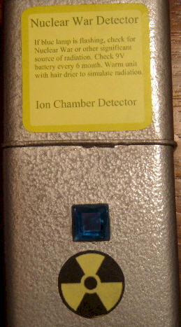
When the unit isn't flashing, it draws virtually no current, so the battery will last its normal shelf life. The unit may be tested by warming the chamber with a hot air gun or hair dryer. Heat it gently and give time for the heat to reach the transistors. The heat will cause leakage within the transistors, simulating radiation and the lamp will flash until the transistors cool again.
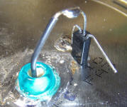
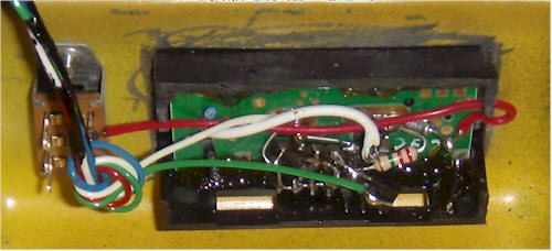
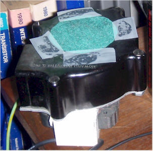
The prototype circuit was built right onto the bottom of the chamber can with the help of a small piece of PCB material. The can is at the positive battery potential and the PCB is at the negative potential. The base of the Darlington is connected to a black insulated wire (see picture below) that passes through a generous hole to a Teflon standoff inside the can. (That black wire could be a 1 meg resistor as mentioned previously.) The standoff also holds a bare wire loop inside the chamber for collecting the ions. The side of the loop isn't critical, and straight wire a couple of inches long is also fine.
After the pickup loop and wire are installed, the can is closed with a piece of tinned PCB material soldered in a few places. Other solderable metal will also work.
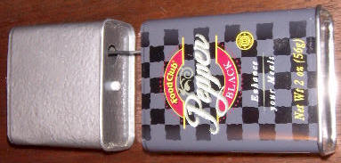
(The views above are the same can but the top photo is after paint.)
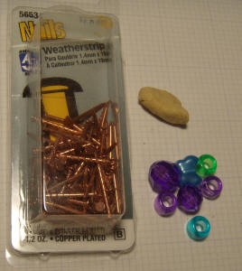
The Teflon standoff may be replaced by a homemade plastic terminal. Those little beads for making necklaces make great insulators although they do have the tendency to melt during soldering. One way to limit the tendency to melt is to secure the electrical terminal in the bead with epoxy putty. The putty insulates the plastic from the soldering heat. Choose a terminal that doesn't conduct heat very well such as a copper-clad steel nail (sold in most home improvement stores). Brass nails also work. Make sure the epoxy doesn't get on the outside of the bead. A wipe with a little alcohol on a paper towel will remove any epoxy residue. To mount the bead, drill a hole in the metal slightly smaller than the bead and run a soldering iron around the hole to heat it on all sides. Press the bead into the hot hole and the plastic will melt. With a little effort, the terminal will be securely mounted with plastic insulation between the nail and metal inside and out. The photos below show the raw materials and a finished terminal.
The
nail can be pushed all the way through the epoxy if a feedthru is desired. For
this project, push the nail all the way through and the base of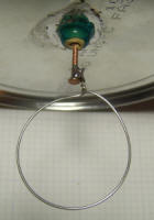 the transistor
may be connected on one side and the little pickup loop on the other side,
eliminating the need for the large hole and black wire.
the transistor
may be connected on one side and the little pickup loop on the other side,
eliminating the need for the large hole and black wire.
 Mounting
a bead in this manner without the epoxy and nail makes a great insulated hole
for wires, too. Just melt the bead into the hole and pass the wire through. Most
wire insulation leaks too much for ion chamber connections and it shouldn't be
allowed to touch metal surfaces. Certain larger "biconical" bead are nice in that
they are tapered and have a ring in the middle that acts as a shoulder but those
with that ring have become hard to find. Heat is applied with a
soldering iron held in the right hand while the can was rotated with the left
hand. The left index finger pushed the bead down with a steady force, requiring
a bit of dexterity. Epoxy may be added for additional strength but make sure
that the epoxy doesn't completely bridge the bead between the can and terminal;
epoxy is too conductive. (These bead photos
are to illustrate the idea but were not used in the Nuclear War Detector
prototype.)
Mounting
a bead in this manner without the epoxy and nail makes a great insulated hole
for wires, too. Just melt the bead into the hole and pass the wire through. Most
wire insulation leaks too much for ion chamber connections and it shouldn't be
allowed to touch metal surfaces. Certain larger "biconical" bead are nice in that
they are tapered and have a ring in the middle that acts as a shoulder but those
with that ring have become hard to find. Heat is applied with a
soldering iron held in the right hand while the can was rotated with the left
hand. The left index finger pushed the bead down with a steady force, requiring
a bit of dexterity. Epoxy may be added for additional strength but make sure
that the epoxy doesn't completely bridge the bead between the can and terminal;
epoxy is too conductive. (These bead photos
are to illustrate the idea but were not used in the Nuclear War Detector
prototype.)
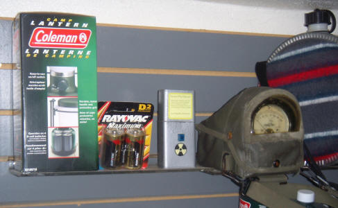
The larger pepper can houses the battery and LED. The battery holder is fashioned from balsa wood strips secured with epoxy and a battery door is cut into the bottom of the can with an abrasive cutting wheel (see photo below). The LED is held in position by its anode lead which is soldered directly to the can. A blue plastic "mosaic" piece from the art store covers the LED hole.
It is easier to paint the cans first then touch up the solder connections later. Try a Q-tip dipped in a little of the spray paint. The finished unit shown below is ever-vigilant on the shelf of the author's bomb shelter, at least long enough to make the picture, anyway.
![]()
Electrometer JFETs were common amplifiers for early smoke detectors and extremely high impedance amplifiers. The most common part numbers are the 2N4117, 18 and 19, with the first having the lowest Idss. All make great amplifiers for homemade ionization chambers. The fact that the gate is a diode junction also makes it practical to discharge the chamber electrode simply by pulling the drain or source of the FET low for a moment, forward-biasing the gate. This feature makes it possible to build sensitive chambers without the need for high-value resistors or specialty relays. The PicAXE Ionization Chamber uses the same microprocessor I/O pin to reset the chamber and then to read the slope of the climbing voltage. Alternately, the rising voltage may simply be detected with a comparator then reset as is done in the Prospector's Ionization Chamber. That project resets the chamber early in its rise to generate lots of reset "clicks" but it's also possible to let the voltage change more between resets for total dose integration as is done in the next project.
![]()
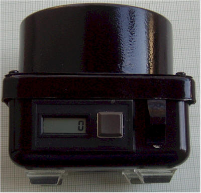
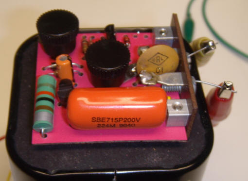
Frankenstein's Dosimeter is so named because it's made from body parts removed from various dead radiation instruments. With a little "spark" of life from a battery, these old components come alive, making a pretty decent radiation dose measurement device. The circuit may be used with a homemade chamber, too; just leave out the three diodes and 2.2 megohm that drive the guard ring (unless your homemade chamber has one).
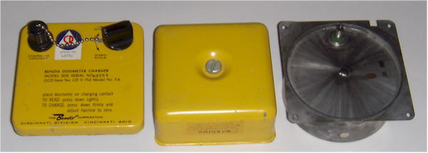
The cylinder on the top is an ionization chamber removed from a CDV-715 Survey Meter. It is mounted on the lid of a CDV-750, manufactured by Bendix. The Bendix version has the screw in the bottom cover, which is necessary for this mod. The power connector and control are removed and appropriate holes are drilled for the ionization chamber feedthru and mounting holes.
The only component left in place is the inductor in the CDV-750; it is used to generate the high voltage for the chamber. The inverter is similar to some of my Geiger counter circuits, but only 50 volts is generated. Current consumption during normal operation is about 50 uA. The inductor is the full winding of the transformer in a CDV-750 dosimeter charger. Find the winding with the highest resistance. Other inductors, 10 mH or above, should work. The zener diodes were chosen to achieve the desired output voltage, but the voltage rating of the diode or diodes will need to be on the high side, due to the very low current. The 1N4715 is a 36 volt zener but only drops about 27 volts in this circuit. Choose a zener family designed for very low current operation. Although ordinary plastic transistors are specified, the actual unit uses metal can types. Just about any transistors will work, as long as the NPN has a breakdown voltage above 50 volts. The parts are mounted on a phenolic terminal strip that was soldered directly onto the lid. Those tiny propane torches make such soldering jobs quick and easy.

Feel free to use any other voltage generator, or even a string of small batteries. The current requirement is virtually zero. I especially like the one I used in the Modified CDV-715 . That circuit uses a 9-volt battery. The battery in this unit is a 6 volt camera type found on a clearance table at the grocery store. Stores dump batteries like these far sooner than necessary and this old battery will power this unit for the next decade.
The circuit below converts the chamber current into pulses for counting. The chamber capacitance plus a little for the JFET is about 17 pF and the CDV-715 manual states that 0.5R/Hr produces about 7 pA. Those values may be used to calculate that 0.5 mR will change the voltage on the gate by 1.5 volts. So, arranging the circuit to reset the chamber after a change of exactly 1.5 volts will yield pulses representing an accumulated dose of 0.5 mR:
500mR/Hr gives 7 pA, so 0.5mR/Hr gives 7 pA/1000 = 7 fA. The voltage on 17 pF would be changing at the rate 7 fA / 17 pF = 412 uV/sec or 1.5 volts per hour. So, 0.5 mR changes the voltage on the capacitance by 1.5 volts.
The 82k resistor sets the sawtooth height and it may be varied to achieve exactly 1.5 volts p-p on the source. You could decide to adjust the resistor for a 3 volt change to get 1 mR pulses, but the pulses are short and might be hard for some commercial counters to register. I decided to double the speed of the pulses and divide them with a flip-flop to get very wide pulses for the slow event counter module I'm using.
When testing the circuit, it's handy to have access to the underside of the chamber, where the pin comes through. That face seems to have thinner materials impeding radiation and laying a radioactive mantle or piece of uranium ore on that face will give a higher reading. Make sure to clean the JFET and guard tube with something like acetone to remove all contaminants. I sprayed a good brand of PCB cleaner up into the tube as a final rinse. If you happen to have used a metal can JFET like the 2N4117A, you can shine a light at the base of the transistor to create a little leakage. Obviously, the transistor should be in the dark when operating. That's a little-known gotcha when using those. Now I consider it a feature!
Note: The guard tube shown below is not electrically connected to the chamber. This shielding tube may be seen in the photo directly below the schematic. By surrounding the sense wire by this tube held at a similar voltage to the gate, any leakage from the 50 volt supply into the JFET's gate is prevented.
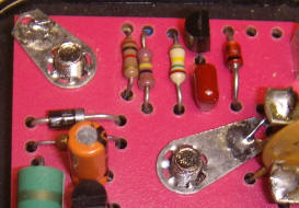
The 3.3 uF can be any value above 1 uF and it connects between circuit ground and the case. Remember, the case is at +50 volts! The 2.2 megohm and three diodes can be directly soldered to the guard tube. My "three" diodes are in a single package (old GE MPD300) and it is obscured by the metal JFET. Metal transistors were used instead of plastic ones, but just about any general-purpose types will work.
Here's how it works:
Radiation ionizes the air inside the chamber and the 50 volts attracts the resulting free electrons and negative ions to the can, and drives the positive ions to the internal plate. The positive ions steal electrons from the plate, slowly increasing the voltage. The source voltage follows the gate, and, when sufficient current flows in the source resistor, the two-transistor circuit in the drain is triggered. That "flasher" circuit suddenly and momentarily pulls the voltage low on the collector of the NPN, and therefore on the drain of the JFET through the diode. The JFET's gate becomes forward-biased and the chamber is quickly discharged. When the flasher circuit reverts to normal, the drain voltage jumps back up and the gate becomes reverse-biased again. This little trick makes it possible to discharge the chamber without any additional components that might pose leakage issues; notice that the only circuit element connected to the chamber wire is the JFET's gate. Use this little trick on homemade chambers, too.
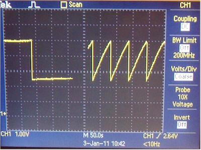
Below is a scope screen of the voltage on the source of the JFET. The first portion of the scope display shows a single reset and slow drift due to leakage and background radiation, and the second portion shows the sawtooth waveform when I place a piece of uranium ore near the chamber. I eventually adjusted the source resistor to get achieve 1.5 volts p-p (2.5 volts p-p in photo).
The counter is a commercial module (CUB3R000) with its own internal battery. (I got a couple of these in a surplus deal, but new ones are probably too expensive.) I removed the battery and cut the case down:
There's a CD4013 flip-flop wired "dead bug" style to divide the pulses by two (1/2 of the IC). This modification is only necessary if your counter can't count the short reset pulses directly. The pulses are big; they drop from 6 volts to nearly 0 volts, so they can be counted in any number of ways, especially with 4000 series CMOS operating from the same battery. The details of the counter are left to the experimenter since my particular configuration isn't likely to be convenient to anyone else. Just find a way to count and display short, negative-going pulses. A little micro would have no trouble.
There's also a sawtooth waveform on the source of the JFET. That's a great place to monitor when testing the circuit. The "PIC enabled" hobbyist could leave out the flasher circuit and connect the drain of the FET directly to Vcc, and use a PIC to measure the voltage on the source. An 82 k source resistor is fine and is not critical. Once the voltage reaches the desired switching point, change the PIC's pin from an input to an output and pull the source low. That will discharge the gate to near zero volts. Then, quickly change that pin back to an input and watch the voltage climb. It will jump up, then ramp at a rate determined by the radiation level. Alternatively, use a different PIC pin to drive the gate of a mosfet that shorts the source of the JFET to ground. The PIC could also measure the rate-of-change of the sawtooth for a current radiation rate measurement (giving both rate and accumulated dose).
![]()
After discovering that one of my bias batteries was jumping around a few volts, wreaking havoc with the readings, I decided to build a floating, regulated high voltage supply. The result is a micro-power 110 volt supply that runs on an ordinary 6V lantern battery. The circuit is similar to my Geiger counter supply but without the additional voltage multiplier on the output. Current consumption in a typical ion chamber setup is only 150 uA (average) so a lantern battery will last a decade, if the shelf life doesn't get it first. No power switch is needed.
The circuit has an output filter consisting of a 100k resistor and a .22 uF capacitor and a typical experiment will have additional capacitance across the chamber, too. To get rid of the last bit of wander as the circuit pulses, increase the 100k to 10 megohm since ion chambers don't draw significant current. I left the value lower in case this device is used to drive a heavier load and added an external 10 meghom in series with the output with a 10 uF polyester capacitor to ground right at the ion chamber. The load can't be too heavy, however. This circuit can just barely drive a 22 megohm resistor with the full 110 volts and a 10 megohm multimeter will load it down to about 85 volts. The .22 uF will still bite you when it's charged and a charged 10 uF will really get your attention! So be careful! If you need better filtering for your chamber, increase the 100k in series with the output to 1 megohm or even 10 megohm - the chambers don't draw significant current.
The circuit bolts right onto the terminals of the battery so I have dubbed this type of circuit a "Battery Topper". Sorry, I couldn't help it! I actually like the idea of mounting handy circuits right on a lantern battery for quick lab circuits. Solder lugs were added to make contact with the battery terminals and narrow nuts were screwed onto the battery first to raise the circuit up a bit so that the hand wiring underneath doesn't press against the top of the battery. The circuit was built on a piece of countertop laminate.
![]()
Here's an interesting accessory to the ion chambers above or other radiation detectors that will allow for the indirect detection of radon gas. Radon is a noble gas and is hard to detect directly; it doesn't react chemically or easily stick to anything and it is usually present in very small amounts. It has a short half-life of under four days so the concentration in a home is due to a constant replenishment as the gas seeps in from the ground or the structure's building materials. Its decay products are much easier to detect because they readily stick to dust in the air and typically have a short half-life, making them more radioactive. This accessory draws air through a filter, catching dust laden with the radioactive "daughters" of the radon present in the air.
An ordinary computer case fan is mounted in one end of a 4" PVC plumbing coupler as shown. This particular fan is held in place by friction but any technique is fine, as long as it pulls air through the coupler. A white poster board doughnut is secured with some foam caulking to seal the gaps along the edges of the fan. The fan is oriented to pull air through a filter affixed to the other end of the coupler with tape. The filter in the picture is a piece of 3M SV-DF01 dusting cloth but other thin dusting or cleaning cloths that will allow a little airflow will also work.
When the fan is running, radioactive dust collects on the outside of the filter. The isotopes of interest all decay within about a couple of hours so they are decaying as they are building up on the filter. At some point, there is enough radioactive material on the filter that the rate of decay equals the rate of collection. This "equilibrium point" is seen as a flattening in the increase in radioactivity.
The filter end of the contraption is placed very near the end of an ion chamber but with a little room for air flow. To get consistent readings, use a single layer of corrugated cardboard as a spacer. Remove the spacer when the filter and ion chamber are both flush against it.
This accessory may be used in two ways. If you have a data taker for your ion chamber, it is interesting to plot the output vs time after you turn on the fan. The radiation will build up, exponentially reaching a steady level. Turn off the fan and the opposite exponential will be plotted. Here's a typical plot:
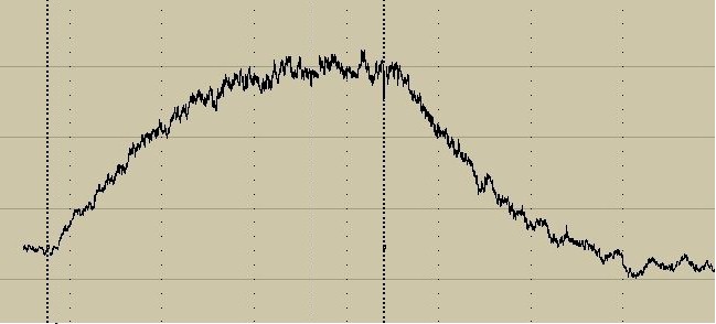
The faint dotted lines are an hour apart and the vertical sensitivity corresponds to about 10 fA of chamber current per division. The fan is turned on at the first marker and turned off at the second marker just after the middle of the plot. The height of the response will depend on the level of radon in the vicinity, the velocity of air through the filter, and a host of other variables. It would be hard to calibrate the response but it could be useful for checking the relative levels in different parts of a house or for periodically checking for significant level changes. Seeing the exponential helps to validate the detection.
Another way to use the gadget is to simply place it in the room to be tested and let it run for a few hours. Then position it up against the ion chamber and make a measurement. It can touch in this case, since no air is flowing. The reading will settle after a couple of minutes. The radiation level will begin to drop after about 15 minutes so don't take too long. Since these isotopes are all but exhausted after a few hours, the filter may be used over and over, until it becomes dusty enough to restrict air flow. The filter should not cause a reading increase when held against the ion chamber at the beginning of a test before the fan has run. If it does, it may be time to change the filter. I simply affixed mine with scotch tape.
Either way you go, a long averaging time is best for the ion chamber so the readings are not bouncing around. My squirrel cage fan pulls a much better vacuum and collects a much higher density of radioactive particles. The radiation was easily detected with an ordinary Geiger counter despite the thick walls of the Geiger tube! Where's my gas mask?
If you want to try a simple experiment to see if this accessory is worth the trouble, try taping a little piece of dusting cloth over the opening of a squirrel cage fan. Let it run for three hours then gently affix it to the aluminum foil window of an ion chamber. I used more tape attached to the original tape because the dusty side of the filter should be against the foil. These experiments are detecting beta particles which have little penetrating power.
The meter reading jumped from near zero to two-thirds scale on my simple darlington chamber. And all this time I thought my house didn't have radon!
![]()
The following is a discussion of the components used in the ionization chambers above. Most of the parts are ordinary resistors and capacitors with no particularly critical specifications, but a few must be chosen carefully.
The JFETs used above are "electrometer" types, typically from the 2N4117 family. They have very low IDSS, usually below 250 uA. Here are a few examples:
|
Part Number |
IDSS |
| 2N4117, 2N4117A, PN4117, PN4117A | 30 to 90 uA |
| 2N4118, 2N4118A, PN4118, PN4118A | 80 to 240 uA |
| 2N4119, 2N4119A, PN4119, PN4119A | 200 to 600 uA |
| Intersil House Number 343A002 | < 100 uA |
| Motorola House Number SPF3059 | 200 uA typ. |
Mosfets are also useful for ion chambers but the vulnerability of the gate to excessive voltage makes them difficult to handle, especially when a long wire is connected directly to the gate. Using a positive voltage on the outer can and adding a resistor in series with the JFET gate helps to prevent damage. If the outer chamber is accidentally shorted to the sense wire, the JFET diode forward-biases, and the resistor limits the current. Larger die JFETs might make interesting front-ends. One obvious choice is the die for the family including the 2N4220 to 2N4224, 2N3821 to 2N3824, 2N5556 to 2N5558, 2N5457 to 2N5459, MPF109 and MPF 111. These FETs will exhibit more leakage than those listed above but leakage should still be well below 1 pA at room temperature. The higher IDSS suggests a higher resistor in the source to set the current to a low level, perhaps selected for a couple of hundred uA. The FET current can be chosen to reduce the temperature coefficient, but the technique can be tricky. Temporarily ground the gate and select the source resistance that gives a minimum change in source voltage when the FET is gently heated with a warm PTC or resistor. Don�t overheat the part to avoid erroneous results. Freeze spray cools the parts too much and the condensation leaks too much, so stick with heating.
Electrometer-grade op-amps are available with leakage currents competitive with the best JFETs. Look up te LMP7721 and LM6001as examples. The op-amp used with a JFET front-end is not particularly critical, and the ordinary LM358 dual op-amp is a typical choice. The circuits above use a "synthetic ground" set to 1/2 the battery voltage and most op-amps that will operate properly on only 9 volts will work well.
High-value resistors are often a problem for experimenters. Companies that manufacture such resistors include Ohmite, Ohmcraft, SRT Resistor Technology, IRC, IMS, Micro-Ohm, and others. High value resistors can also be found in older equipment like the CDV-715 survey meter. Most experimenters collect such resistors by cannibalizing old equipment or by finding them on an auction site. The prototypes above use either carbon film or metal film resistors for the lower values. Metal film resistors are hard to beat, exhibiting excellent accuracy and temperature stability, but most of the resistors aren't critical. The power dissipation is low for all of the resistors, usually well below 1/4 watt. The 390 ohm resistor supplying the 9 volt zener dissipates a little over 300 mW.
The Darlington transistors used above are garden-variety types but very old parts may not exhibit the amazingly low leakage of modern devices. The gain of one MPSAW45A was verified to be over 30,000 down to picoampere inputs and the leakage might be as low as 100 fA at room temperature.
Large non-polar mylar capacitors, perhaps 1 uF, are suitable for bypassing the chamber voltage to the battery negative voltage ("ground"). The use of a non-polar capacitor allows the polarity to be reversed for experimental purposes. For example, the background radiation can be distinguished from zero offset or leakage by reversing the voltage on the outer can and measuring the change in the output. A microprocessor or computer could change the voltage with a relay then measure the current change after sufficient settling time.
The super capacitors used to filter the meter and output can be expensive if purchased new, but they are fairly common on relatively modern surplus circuit boards. Their application above was more of an afterthought, but it is fun to use such components in unexpected ways. They feature very low leakage so the time constants can be extremely long without significant error.
Teflon terminals are excellent for these projects but the common styrene necklace beads work great, even the ones with the metallic glitter inside. Other phenolic or ceramic terminals should be avoided or at least thoroughly tested. Most glasses have too much surface conductivity, too. The softer plastic 5-way binding post used for the first chamber is questionable but seems to work well enough.
The best choice for the chamber is the tin alloy typically used for cookie tins. They are easy to work and take solder beautifully. Watch those sharp edges, however. Many of these cans have an epoxy lining that forms an insulation layer. Surprisingly, charge doesn't seem to accumulate on the surface; like most materials, it's probably too conductive (which is good in this case). The epoxy should block alpha emissions from the metal alloy. Avoid un-plated cans and keep soldering to a minimum on the inside since some solders have significant quantities of radioactive contaminants.
These simple ionization chambers are the "crystal radios" of radiation detection. They are truly simple to build and really work. They respond to any ionizing radiation that can get inside the chamber from 100 nm ultra-violet light through X-rays and gamma-rays. They also respond to alpha (helium nuclei) and beta (free electrons or positrons) radiation if provisions are made to allow them inside the chamber. Alphas can't even make it through a piece of paper so a wire mesh or placing the sample in the chamber is best. The serious hobbyists can find a wealth of literature for improving these simple designs, converting them into serious scientific instruments.
![]()
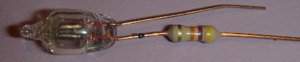
I was intrigued by the idea of using an ion chamber with a bit of radioactive material inside as a resistor-like circuit element for very high impedance circuits. But as I was getting ready to try it, I remembered various discussions about NE-2 and similar neon bulbs containing a radioactive element to help the bulbs start. So it seemed that a simple neon lamp might be a nice resistor. I connected a bulb to a leakage meter and measured the current for various voltages across the lamp. The bulb was kept in the dark during the experiment. The "resistance" measured about 300 gigohms with 4 volts across the bulb. To make sure I wasn't measuring leakage along the glass, I snipped off the top of the bulb to "let out the radioactive gas". To my surprise the resistance dropped in half. It turns out that the electrodes in the bulb are slightly radioactive, probably due to added thorium. My Geiger counter jumped from 10 CPM to 60 CPM when the elements were held near the mylar window of the tube. The air must provide a better "target" than the rarified neon gas for the radiation to make ions which is why the resistance dropped when I snipped off the top of the bulb.
With a low voltage across the neon lamp, most of the ions have time to recombine before reaching the electrodes and this gives the bulb a resistor-like characteristic curve. I would expect the current flow to level out at some potential as all the ions reach the electrodes. So this resistance isn't particularly linear and probably varies from bulb to bulb but many projects just need a really big resistor to pull some low voltage node toward a known potential. For example, you might want to pull a gate of an FET to ground with a high value resistor to maintain a high input Z and a neon lamp like this might by perfect.
To prepare the bulb, clean it with a good solvent like lacquer thinner or acetone and keep it in the dark when in use. I have successfully painted a bulb with black enamel which helps but I had to mask off the area near the leads because the paint is too conductive. A black plastic box would be a good idea. Close the box on the leads and then heat the leads with a soldering iron so that they melt into the plastic, allowing the box to close fully. Most plastics are excellent insulators. Also, keep the inside of the entire project's case dark.
I wiggled the electrodes of the neon bulb back and forth until they broke off. Now, all that was left was the leads and the glass base. I measured the resistance and got a reading in excess of 20,000 gigohms so the surface of the glass isn't a significant player, at least for that bulb. The resistance might be even higher than that; I just didn't have the patience to wait for the slowly drifting meter! The leakage meter really slow down when the resistance gets that high.
I checked a few more lamps and found great variation between them. They seem to vary between a couple of hundred gigohms to over 5000 gigohms. That's a lot of variation within a batch of identical-looking lamps! Keep these variations in mind. After testing some other types of lamps, I've concluded that there is a wide variation in the amount of radioactive element in the lamps. I was somewhat surprised to be able to easily measure the radioactivity from those tiny electrodes of the first lamp I tested. That bulb was unusually hot. More info: I tested the two tiny electrodes individually and found that only one of them is really hot, probably due to manufacturing variations.
So, there you have it; a box of neons with radioactive electrodes is actually an assortment of resistor values. Well, for a few years anyway.