![]()
|
My Introduction to these simple devices, failures and all. Don't build these, just read about them! | |
|
Very Large Cookie Tin Version features a somewhat improved circuit but build the next one instead. | |
|
Modify a CDV-715 Survey Meter for High Sensitivity a difficult modification but the circuit is great for homemade units. | |
|
Super-Sensitive Ionization Chamber a really nice version that performs quite well. Some of the mods are a bit strange. |
Other pages of interest:
|
Ionization Chambers (page 1) featuring high-value resistors as feedback elements. | |
When ionizing radiation (far ultra-violet light, x-rays, alpha and betya particles, etc.) pass through a gas, collisions with the gas molecules produces ion pairs, typically charged molecules and free electrons. If an electric field is present, the ions will move apart, each moving in opposite directions along the electric field lines until they encounter the conductors that are producing the electric field.
An ion chamber is an extremely simple device that uses this principle to detect ionizing radiation. The basic chamber is simply a conducting can, usually metal, with a wire electrode at the center, well insulated from the chamber walls. The chamber is most commonly filled with ordinary dry air but other gasses like carbon dioxide or pressurized air can give greater sensitivity. A DC voltage is applied between the outer can and the center electrode to create an electric field that sweeps the ions to the oppositely charged electrodes. Typically, the outer can has most of the potential with respect to ground so that the circuitry is near ground potential. The center wire is held near zero volts and the resulting current in the center wire is measured.
The voltage required to sweep the ions to the conductors before a significant number of them recombine or stick to a neutral molecule is usually under 100 volts and is often just a few volts depending on the dimensions of the chamber. The resulting current is extremely low and detecting individual particles is difficult, especially with ordinary air at atmospheric pressure. The simple chambers to be discussed respond primarily to beta particles and, if they can get inside, alpha particles. Most other rays don't cause enough ionization to be easily detected. These room-pressure chambers respond to the average level of ionizing radiation and do not provide "clicks" like a Geiger counter tube.
Sensitive homemade ion chambers for detecting nuclear radiation are fairly easy to build but the circuitry is tricky and should only be attempted by "seasoned" experimenters - the currents are likely to be well below 1 pA unless there is a serious nuclear war in progress! (The simple version is "beginner friendly"!) Special electronics is needed at the front end, typically called an "electrometer" circuit, which produces an output voltage in proportion to the input current. The electrometer must have a very low bias or leakage current to avoid masking the desired signal and the intrinsic impedance of the amplifier must be extremely high. The input impedance of the electrometer may be fairly low, however, using feedback to convert the tiny current into a usable voltage.
Older designs used special electrometer tubes like the 5886 which requires only 10 mA at 1.25 volts for the filament and about 10 volts for the plate. These tubes are great for the experimenter because they are relatively immune to static discharge and they consume about the same amount of power as a typical transistor stage. Some electrometers use vibrating capacitors or mechanical choppers to convert the tiny DC currents into AC before amplification to avoid DC bias and leakage problems. Newer circuits typically use MOSFETs or Electrometer grade JFETs in the front-end. MOSFET op-amps usually contain protection diodes which can be responsible for several picoamperes of leakage at room temperature and a fairly steep increase in leakage as the temperature increases but in some ion chamber applications this extra leakage is tolerable. Non-protected MOSFET front-ends are easily damaged by static electricity and special low-leakage protection diodes are usually added. Low current JFETs like the 2N4220 give respectable performance and the types intended for electrometer applications like the 2N4117A are quite impressive, exhibiting leakage well below 1 pA. They have the added benefit of being significantly less sensitive to static electricity than unprotected MOSFETs. Full ESD precautions must be observed with any of these approaches!
As mentioned earlier, most electrometer circuits use feedback to reduce the effective input impedance and to direct the tiny input current through a very large feedback resistor such that a reasonable voltage is produced at the output. The feedback resistor must be quite large, however. If the input current is 1 pA and the feedback resistor is 100 megohms, the output voltage will only be 100uV. Special resistors measuring in the millions of megohms are available but are usually difficult for the experimenter to obtain (see http://www.ohmite.com/catalog/v_rx1m.html , for example).
An extremely sensitive circuit was desired that didn't require special resistors and that didn't fail every time a slight ESD mistake was made and the result is the experimental circuit shown below. It uses a 2N4117A as the input amp and another as the feedback resistor. If one studies the tiny curves supplied in the data books and uses a little "extrapolation" and imagination, the leakage of the 2N4117A with the drain and source connected together can be seen to have a slope equivalent to about 75 million megohms! There is unit-to-unit variation and it is necessary for the input JFET to have lower leakage than the feedback JFET so the circuit is not for everyone. (If the input JFET leakage is higher, the output voltage will be very low. Simply swap the JFETs.) The FETs are easily damaged, too, which can lead to frustration when the "best one" gets zapped. The circuit will not be particularly accurate since the actual feedback resistance is not known (nor linear) but the experimental ion chamber is not easily characterized anyway. Despite the circuit's shortcomings, it is extremely sensitive and surprisingly stable. A "good one" might drift only 0.1 fA in a day if ambient conditions are relatively constant. (That corresponds to about 10 mV drift on the output.) The short-term variation is below 1 mV which corresponds to 0.01fA! If the ion chambers really work, this circuit should be able to see the current!
The input FET (the one on the right) and the two transistors form an "error" amplifier that attempts to maintain the drain voltage at 10 volts (set by the resistor divider in the emitter of the NPN). If current flows out of the ion chamber causing the gate voltage to rise, the drain will begin to drop and the voltage on the collector of the NPN will go up. This rise will decrease the current in the PNP and thus lower the output voltage. The voltage drop across the first "resistor" FET will increase and more current will flow through it - nearly all of the ion chamber current, in fact. There is sufficient loop gain that the input voltage does not change very much and most of the ion chamber current flows through the feedback FET. The zener in the source of the input FET moves the gate voltage operating point up above ground so that dual polarity supplies are not needed. The output voltage should be a few volts, perhaps 3 or 4, depending upon the relative leakage of the FETs. If the voltage gets too near 6 volts, the sensitivity will drop and the response will become more logarithmic (which might be useful for some applications). If the voltage is too low, the circuit might "bottom out" and loose control. There isn't much that can be done to set the operating point expect swap out FETs! The glass around the FET leads must be VERY clean. Use a good solvent to remove any contaminants.
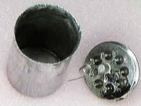 The first experimental ion chamber was made with a zinc can from a D-cell battery and
an old 8-pin glass-to-metal header as seen in the photo. The two FETs were mounted
inside the chamber with the theory that this would eliminate the problem of connecting the
extremely high impedance probe to the outside world without creating leakage paths to
ground. The problem with the concept is that the transistor bodies and leads compete with
the wire for the free ions. Carefully painting the transistor bodies and legs with
conformal coating helped but the circuit will not tolerate the coating around the
gate of
the transistor - it is too conductive! (In retrospect, the transistors should reside in
their own can with the sense wire passing though a hole into the ion chamber which is what
the schematic shows.) The pickup wire should be thin and near the center of the can to
keep the capacitance low so the response time is as short as possible. When power is first
applied, it can take a very long time, maybe 20 minutes, before the circuit settles out to
a steady reading. At first, about 150 volts was applied to the can but it was soon
discovered that only a few volts are adequate and a 9 volt battery was used instead. The
15 volt power supply voltage should be fine for most ion chamber sizes. If the voltage is
too low, the readings will be low as the ions have time to recombine before being swept to
the electrodes.
The first experimental ion chamber was made with a zinc can from a D-cell battery and
an old 8-pin glass-to-metal header as seen in the photo. The two FETs were mounted
inside the chamber with the theory that this would eliminate the problem of connecting the
extremely high impedance probe to the outside world without creating leakage paths to
ground. The problem with the concept is that the transistor bodies and leads compete with
the wire for the free ions. Carefully painting the transistor bodies and legs with
conformal coating helped but the circuit will not tolerate the coating around the
gate of
the transistor - it is too conductive! (In retrospect, the transistors should reside in
their own can with the sense wire passing though a hole into the ion chamber which is what
the schematic shows.) The pickup wire should be thin and near the center of the can to
keep the capacitance low so the response time is as short as possible. When power is first
applied, it can take a very long time, maybe 20 minutes, before the circuit settles out to
a steady reading. At first, about 150 volts was applied to the can but it was soon
discovered that only a few volts are adequate and a 9 volt battery was used instead. The
15 volt power supply voltage should be fine for most ion chamber sizes. If the voltage is
too low, the readings will be low as the ions have time to recombine before being swept to
the electrodes.
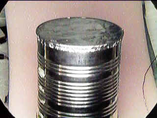
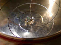
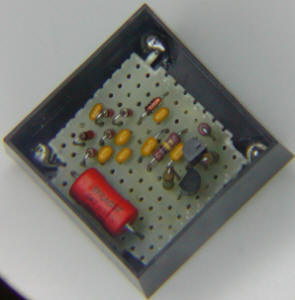
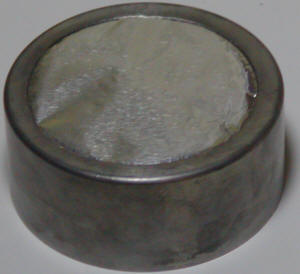
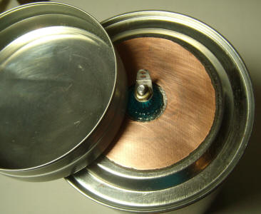
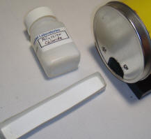
To test the chamber, a 1.3" diameter disk of radioactive material (a calibration disc from an old Geiger counter) was leaned against the can. The voltage changed a few 10s of millivolts but I quickly lost interest in this chamber when the lid slipped and zapped the FETs. I had already spotted an old mint can at the back of the workbench which I liked better for a chamber. (See pictures below.) An audio connector was added to the center of the 3" dia. tin can and the FETs were mounted directly to the pins. A ring of wire was used for the center electrode. The insides were washed well with a solvent and then dried with a hot air gun before the base was added and tack-soldered. (I should have removed the plastic coating on the inside of the can.)
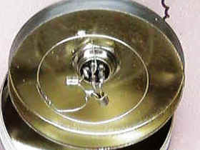
Little feet were added to the bottom of the can so that I could easily slip my radiation disk underneath without disturbing the chamber. This ion chamber gave gratifying result: the little radiation source gave an output voltage change of about 70 mV which was very large compared to the meter wander of about 2 mV.
At this point in the festivities, I decided to try a crude calibration. Really crude. My calibration reference was a Heathkit Geiger counter which has a meter that reads counts per minute and mR/ hour. The scales are a little suspicious since the CPM scale is an exact power of 10 bigger than the mR/hr scale. (0.3 mR/hr = 300 CPM on the X1 scale, for example.) It is entirely possible that the Geiger tube dimensions were selected to achieve just this result. In the past I had compared this Geiger counter against another "bomb shelter" type and obtained surprisingly close readings - maybe within 10%. The radiation disk gives 1500 CPM when held directly against the Geiger tubes mylar window and 500 CPM when the lid of a mint can is placed in between (to simulate the ion chamber walls). The background radiation measured about 13 CPM. Now here is where the calibration gets a bit "iffy". The disk is large compared to the Geiger tube window but it is small compared to the diameter of the ion chamber. To make a long story short, the ion chamber will read low by some factor - maybe 4. What I think it all means is that the ion chamber gives about 6 mV for a radiation level that causes about 10 CPM in the Heathkit unit corresponding to 0.01 mR/hr. The background radiation should give a reading just above 2 mV which is about how much the readings wander from minute to minute. Another big question mark arises from the fact that the ion chamber responds to beta particles but the Geiger tube is also somewhat sensitive to gamma rays. This calibration may be within one order of magnitude! "Calibration" is a bit meaningless anyway when talking about such a zoo of different particles each with different energy.
![]()
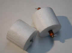
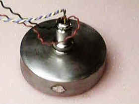
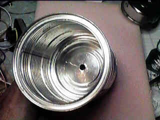
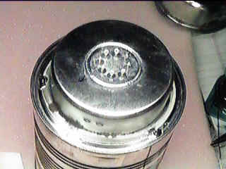
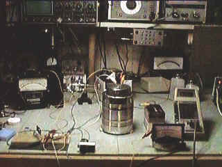
But now I am hooked. I want an ion chamber that can easily see the background radiation. To make a bigger chamber, I chose a 4.5" by 4" diameter peanut can (see below). I also decided to move the FETs into their own compartment. For this compartment, I used a steel wheel from the center of an electronic component reel. Any small can would work here, but this piece fits nicely on the bottom of the peanut can and it had a hole perfect for the 8-pin header that I happen to have in large quantities. A hole was drilled in the bottom of the peanut can for the electrode. No insulator was used - just the air gap. You can see the wire sticking up from the FETs in the first picture and the wire is visible passing through a hole into the chamber in the second picture. The end of the peanut can was sealed with aluminum foil to keep out air currents and electric fields but to allow less energetic or larger particles in.

The voltage on the outer can was increased to 22.5 volts by using an old 'B' battery on the theory that a larger chamber would need a larger field to sweep out the ions quickly enough.
 After power was applied and sufficient settling time went by (about 15 minutes), the
meter reading was seen to be significantly more jumpy. The FETs were the same ones from
the previous chamber and great care was taken to keep everything clean so I immediately
suspected that I was seeing individual ion trails. When I slipped the radiation disk under
the aluminum window, the reading climbed to a whopping 1.5 volts! And what a coincidence!
The Heathkit gives a count of 1500 CPM for this same source when covered with aluminum
foil. (Actually, the foil hardly attenuates the radiation coming from the disk.) So now I
have a direct readout of mR/hr: 1 volt = 1 mR/hr. Unfortunately, I have not yet
corrected for the much larger detector area of the new chamber but it works out to be
nearly 10! So the sensitivity of the new chamber is 1 volt per 0.1 mR/hr which is pretty
sensitive! Again, I'm ignoring the different sensitivities to different types of
radiation. The radioactive element from a smoke detector was held up to the Geiger counter
and the count soared to about 22,000 CPM but placing a piece of aluminum foil in between
dropped the count to 200 CPM. The ion chamber gave a reading of 200 mV which is in perfect
agreement. But I didn't expect agreement since this source is small relative to the Geiger
tube, also. The mylar window on the Geiger tube significantly blocks the alpha particles and this
may account for coincidental agreement. These "calibrations" are really coarse! By using the Geiger
counter to measure the background radiation it was determined that the ion chamber should
be indicating 13 mV but since the zero setting is arbitrary, it was hard to confirm this
level. Reversing the polarity on the outer can caused a shift of about 30 mV (after
several minutes of settling) which is about what is expected if the background is near 15 CPM (plus 15 to minus 15 is a total of 30). The experimental setup is shown below:
After power was applied and sufficient settling time went by (about 15 minutes), the
meter reading was seen to be significantly more jumpy. The FETs were the same ones from
the previous chamber and great care was taken to keep everything clean so I immediately
suspected that I was seeing individual ion trails. When I slipped the radiation disk under
the aluminum window, the reading climbed to a whopping 1.5 volts! And what a coincidence!
The Heathkit gives a count of 1500 CPM for this same source when covered with aluminum
foil. (Actually, the foil hardly attenuates the radiation coming from the disk.) So now I
have a direct readout of mR/hr: 1 volt = 1 mR/hr. Unfortunately, I have not yet
corrected for the much larger detector area of the new chamber but it works out to be
nearly 10! So the sensitivity of the new chamber is 1 volt per 0.1 mR/hr which is pretty
sensitive! Again, I'm ignoring the different sensitivities to different types of
radiation. The radioactive element from a smoke detector was held up to the Geiger counter
and the count soared to about 22,000 CPM but placing a piece of aluminum foil in between
dropped the count to 200 CPM. The ion chamber gave a reading of 200 mV which is in perfect
agreement. But I didn't expect agreement since this source is small relative to the Geiger
tube, also. The mylar window on the Geiger tube significantly blocks the alpha particles and this
may account for coincidental agreement. These "calibrations" are really coarse! By using the Geiger
counter to measure the background radiation it was determined that the ion chamber should
be indicating 13 mV but since the zero setting is arbitrary, it was hard to confirm this
level. Reversing the polarity on the outer can caused a shift of about 30 mV (after
several minutes of settling) which is about what is expected if the background is near 15 CPM (plus 15 to minus 15 is a total of 30). The experimental setup is shown below:
More Experiments:
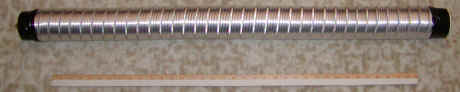
I tried a long chamber made from a section of air duct with a thin wire stretched between two Styrofoam plugs:
|
The internal wire was soldered to both ends, the plugs taped in place and the tube stretched to tighten the wire. |
| The finished detector was pretty awful! First of all, the electrostatic shielding on the ends was inadequate, causing a huge 60 Hz signal. And, the wire would vibrate with the slightest bump causing wild swings in the output. Maybe this thing might be the start of a seismometer, but it stinks as an ion chamber! |
|
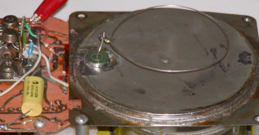
Another chamber was constructed with a large cookie tin similar to the peanut can design above. The performance of this much larger chamber was excellent. A single Coleman lantern mantle nearly "pegged" the output. The background radiation gives about 4 mV (400 mV after amplification) which corresponds to 40 fA current. (Some CMOS op amps have input current below 40 fA like the LMC6001 and would work fine without the JFET.) Even though the circuit was given a low frequency response to reduce 60 Hz response, the meter jitters in response to individual ion trails. (The superior shielding of the cookie tins would probably allow for a faster response, if desired, but watch out for circuit instabilities.)
| This tin measures about 10.5" across and about 6" tall (a "regular" height tin should work as well). The center portion of the lid was cut out with scissors to make a frame to hold the aluminum foil window. The circuit is housed in a smaller cookie tin tack-soldered to the bottom. Connections are made via a 5-pin audio connector. | 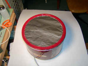 |
 |
 The electrode looks like a
lasso. The electrode looks like a
lasso. |
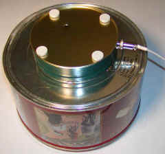
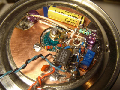
The electrode is a 5" dia. wire ring mounted to a Teflon standoff and a short piece of stiff telephone wire connects the electrode to the circuitry. The wire passes through a large hole without touching the sides to reduce the chances for leakage currents. The circuitry is a modified version of the first schematic featuring a resistor for the feedback and an op-amp for boosting the output signal. The transistor circuit was also modified to increase the loop gain and improve the stability (see ckt. desc. below). | |
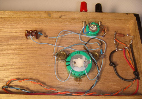
| A word of caution: the metal sure looks like ground and a person (um, like me) might start soldering components that go to ground to it. The can will actually be connected to +45 volts or more so the "ground" connections are made above the metal. The only components that connect to the can in the photo are a large yellow cap and a couple of white caps used to support my elevated ground buss. | 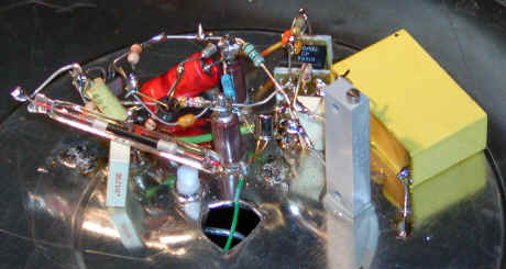 |
|
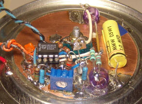
The new circuit includes several improvements. The feedback FET is replaced with a Victoreen 100,000 megohm resistor which is the long glass tube in the photo. A zener diode was added to the emitter of the 2N4401 to increase the loop gain and a .01 uF Miller capacitor was added to reduce the amplifier frequency response (for stability and to reduce 60 Hz gain). An op-amp (OP-07) was added to boost the output by a factor of 100. The "zero" pot is used to set the output to a few volts since the OP-07 cannot swing below 1 or 2 volts out without a negative supply. This pot must be able to be adjusted to the gate voltage and with some FETs the voltage may not go low enough. The symptom will be a high op-amp output voltage. If so, just lower the 10k resistor or add a 1k above the pot. An additional zero pot for the meter could be added as in the first schematic to get a near-zero reading for the background radiation, if desired. If your circuit is unstable add a 330 ohm resistor in series with the emitter of the 2N4403 and remove the 0.01uF capacitor on the collector.
Notice that the drain resistor was reduced to 125k. This value was experimentally determined by finding the drain current that gives the 2N4117A a near-zero temperature coefficient. The test circuit is simple: connect a sensitive current meter from +10 volts to the drain, ground the gate, and connect the source to ground through a 500k pot. The current is observed at room temperature then the FET is warmed and the current change is noted. The pot is adjusted until little or no change occurs. I heated the FET by touching a warm PTC to the can - probably reaching about 65 degrees Celsius and the final current change was below the current change caused by a 100 uV gate voltage change. (Corresponds to less than 1 fA ion chamber current for 40 degrees.) Room temperature may vary by +-4 degrees which would correspond to a wander of 0.1 fA which is well below the 40 fA background current from the chamber. The bias current that gave this wonderful temp-co was 40uA and since the drain resistor will have 5 volts across it, the desired resistor value is 5/40 uA = 125k. "Your results may vary." Actually, the FETs are surprisingly stable at all currents and the whole procedure may be unnecessary; just use 125k!
Also consider the circuit used in the CDV-715 mod below. The mod is hard but the circuit is easy. Also, my circuits use ultra-low leakage JFETs because I have about a thousand of them but there are also op-amps that can do the job directly. Investigate the LMC6001 (25 fA, tested!). Just leave the FET and source resistor out of the CDV-715 circuit below and connect the negative input of the op-amp directly to the sense wire. Don't connect the 33k battery test resistor.
A 22.5 volt battery was insufficient to capture all of the ions but two batteries (45 volts) seemed to do the job - in other words, higher voltage did not result in a higher reading. Higher voltages may be desired for observing individual events, however, since the ions will be swept to the electrode faster.
Parts Notes:
| The 4.7uF capacitor should be a non-polar film type with a voltage rating above the voltage used (45 volts in the schematic). A non-polar type allows the voltage polarity to be reversed for experimental purposes. | |
| The 100,000 megohm resistor is a specialty device which may be hard to obtain. | |
| The 2N4117A is an unusual electrometer-grade JFET which has few substitutes. | |
| The other components are not particularly critical. |
A commercial Geiger tube is pretty hard to beat for general radiation monitoring but the simplicity and versatility of a homemade ion chamber that requires no special gasses or pressures makes it an attractive alternative for many experiments.
![]()
This project endeavors to modify an ion chamber style radiation meter, the CDV-715, so that it has useful sensitivity, taking advantage of the internal ion chamber, high value resistor, and nice packaging. The new circuit increases the electrical gain by 1000, converting the scales from R to milli-R. I decided to abandon virtually all of the existing electronics for several reasons. The chamber current is converted into a voltage by switched resistors but the ceramic switch will simply leak too much; it can only be used for range switching after amplification. There is no need for 1.5 volts since there will be no filament to heat so the inverter that converts 1.5 volts to 50 volts and 10 volts will be unnecessary. A 9 volt battery will power the electronics and a unique version of the Cockcroft-Walton voltage multiplier will generate the 50 volts for ion chamber bias. The electrometer tube will be replaced by a very low leakage JFET and a micro-power op-amp to save power. According to the manual for the CDV-715, the output should be about 14 femto-amperes per mR/hour, a pretty tiny current. Using the 220,000 megohm resistor already in the instrument, the corresponding voltage will be about 3 mV per mR/hour which isn't completely unmanageable. If the 100X switch setting is to become 500mR full-scale, the voltage will still only be 1.5 volts when the meter pegs. So, no range switching is needed at the input.
Note: Add a 1 megohm in series with the gate lead of the JFET to reduce the chances of damaging it. The resistor will have no impact on performance.
In order to take advantage of the instrument's calibration, the
ion chamber should be biased at 50 volts as is done by the original circuit.
A modified Cockcroft-Walton voltage multiplier driven by an astable
two-transistor flip-flop boosts the 9 volts to 50 volts. This inverter circuit
draws only 100uA but for even less overall power consumption, five 9 volt
batteries could be added in series with the main battery to get 45 volts. These
batteries could be tiny 10A size batteries with no power switch since there is
virtually no current required. I potted my inverter with wax in a little plastic
box:
The voltage output is a fraction of a volt below 50 volts with 9 volts power; just right! A very high impedance voltmeter is required to accurately measure the voltage; an ordinary 10 megohm meter will load the voltage down to about 35 volts. As the wax was cooling, I dropped a piece of tinned copper-clad board on top of the wax to serve as a bottom cover and I soldering a couple of wires onto the copper that line up with some of the holes on the PCB for mounting.
I removed all but a couple of the components on the original circuit board, leaving only the 5.6 meg resistor and 0.1uF capacitor used for filtering the 50 volts. I don't show them on the schematic but they are between the 50 volt inverter and ion chamber. Feel free to leave them out; they aren't really doing much. I mounted the 220,000 megohm resistor to a new terminal bolted to one of the switch mounting holes. The other end of the resistor has a large diameter socket for the pin of the ion chamber and a smaller socket soldered on sideways for the JFET gate. Sockets make it easy to assemble the unit and make it easier to change the JFET after you accidentally zap it. The problem is that the chamber is at 50 volts and stays charged for a while after power is removed. The charge is sufficient ot zap the JFET if it is discharged through the gate. If you decide to not use sockets for the JFET, turn power off and discharge the chamber to the negative of the battery every time you start working on the insides or be prepared to solder in a new one! (I lost several - bad habits die hard.) I used two traces right below the JFET for its drain and source, cutting them to make two isolated pads. The sockets are sticking up because they will hit the ion chamber if they stick out the bottom of the board.
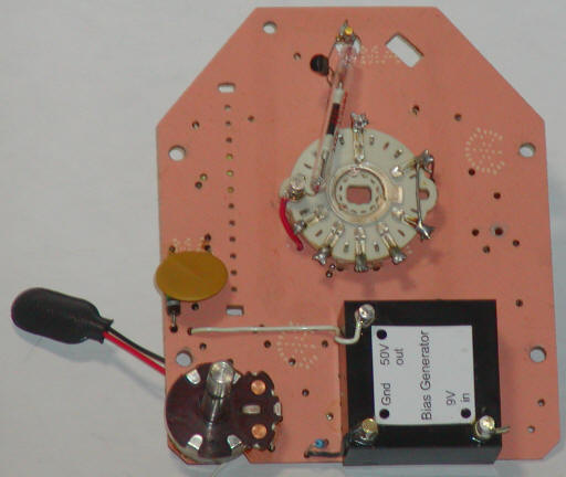
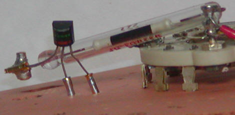
Attention! it's a great idea to insert a 1 megohm resistor in series with the gate. In the above picture, the wire from the JFET to the socket would have this resistor in series. This resistor will reduce the number of JFETs you destroy trying to get it working! The resistor will not alter the performance.
The op-amp circuit is built on a piece of tinned copper-clad board. One op-amp is used to generate V/2 (4.5 volts) and the other is the feedback amplifier. I used two single micropower op-amps but a dual CMOS type would be fine. I like micropower types to give the best battery life but an ordinary LM358 should be fine.
I used the switch section with the terminals sticking up (where the high-value resistors were connected) for the power switch and the switch terminals mounted in the PCB for the range switch. The three resistors that set the range may be mounted in the holes where the cal pots were located. However, cut away the trace on the wiper terminal located near the ion chamber pin because that trace goes other places. Feel free to figure out a completely different switching scheme.
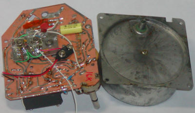
If you use the chamber as-is you might have a roughly calibrated unit but if you want maximum sensitivity to any radiation, you may want to modify your chamber. I unsoldered the chamber holding it over the stove (after removing the solder plug in the center to let out pressure). It took two oven mitts and a bit of effort. The heat partially melted the internal plastic liner and the exhaust fan was quickly turned on. I removed the liner and the metal plate, drilled a large hole in the lid, nearly the full diameter, and replaced the disc electrode with a wire loop:
To make the foil window I cut aluminum foil to the outside diameter so that it folded up at the edges when inserted from the back of the can. I then added a band of tin (length of grounding strap) to press the foil against the side and bottom of the can and tack-soldered the tin band into place while pressing. A little conductive silver paste insured good electrical contact and a little bead of glue sealed the seam. In order to take advantage of the thin foil window, I cut a 3" round hole in the bottom of the case directly beneath the ion chamber and covered the hole with some wire mesh. Remember, chopping up the chamber like this destroys any "calibration" but makes the unit much more sensitive.
I reinstalled the battery holder after installing a metal 9 volt battery clip inside. A battery snap connects the battery to the circuit. Total current is about 400uA.
The result is a very sensitive detector! On the X10 scale a single lantern mantle will give a reading of 1 on the meter and there are two more sensitive ranges! (There is a mantle beneath the unit in the picture above.) On the X0.1 scale the meter occasionally jumps up to mid-scale when a "big one" strikes and it gives a 1/2 scale reading for a mantle 5 inches away! There is no provisions for zeroing the meter but setting it near the bottom of the scale on the X0.1 scale seems adequate. The zero pot is touchy on the most sensitive scale and you may wish to tame it down by increasing the series resistors once you know the required voltage. I soldered a wire from the case to the 50 volts, making it long enough to allow the case to be set to the side with the unit open. Alternately, a spring contact could be added to make contact between the case and lid. The round metal plate that was in the ion chamber could be used as a beta blocker by placing it between the aluminum window and the wire mesh. It would be a good idea to add a fresh desiccant packet to the inside of the ion chamber since humidity impacts the sensitivity. I didn't solder the ion chamber back together since it was such a snug fit so it is relatively easy to open for changing desiccant packets. I think I'll add a clip on the inside of the chamber to hold one. You could just seal the chamber really well but pressure changes might cause problems with the aluminum window. I just had an idea: there is a little solder-covered pinhole in the middle of the back of the ion chamber that could be used as a breather hole. Seal the chamber really well, leaving that little hole open. Now, somehow affix a little metal or plastic box over that hole big enough to hold a desiccant packet. Poke a little breather hole in the box and the air will have to pass through the desiccant to get into the chamber. I'll work on that.
I don't know if all this is worth the trouble but now we know it can be done!
![]()
Improved performance may be realized with an electrometer JFET or ultra-low leakage CMOS op-amp in place of the Darlington transistor. This detector features an old-fashioned electrometer JFET transistor like those commonly used in early smoke detectors, pH meters and electrometer amplifiers. The leakage in these FETs is remarkably low, typically below 25 fA, depending on the package and surface contamination.
One of the op-amps in the LM358 is used to generate 1/2 the battery voltage near 4.5 volts to be used as a virtual ground. When the meter reads zero, the gate of the FET will also be at 4.5 volts. The source will be at a slightly higher voltage due to the FET characteristics, and the zero pot applies a voltage to pin 3 that is set to that source voltage. This voltage will depend on the individual FET. As a starting point, short the large value resistor and measure the source voltage. Select the resistor to get that same voltage on pin 3 with the pot at its center position. Don't be concerned if you need a much larger resistor than 5k, even approaching 82k, but the source voltage shouldn't be much above 4.5 volts, perhaps 6.5 volts at the most with higher Idss parts. Reduce the 121k (not a critical value, by the way) for experimenting with higher Idss FETs to keep the source voltage below 6 volts.
Specialized op-amps are also available with similar leakage properties to electrometer JFETs (see the National LMC6001, for example). To use such an op-amp, simply leave out the FET and connect pin 2 directly to the 1 megohm resistor. However, extreme caution must be used to prevent the wire from touching the can or the op-amp may be destroyed. The 1 megohm resistor protects the rugged FET, but it may not protect many op-amps. Don't use a high voltage on the chamber with an op-amp directly connected to the sense wire, or the turn-on surge will likely damage the op-amp. (JFETs are especially good about this, since the gate forward-biases during turn-on.) With only an op-amp, it may be desirable to connect the selected resistor from the pot to zero volts instead of 4.5 volts since the required zeroing voltage will be near 4.5 volts. Another 100k resistor would be a good choice. In fact, the pot may not be necessary at all; simple connect pin 3 to the 4.5 volts from the other op-amp.
In order to convert the very tiny chamber current into a reasonable voltage, a very large resistance is needed. This prototype uses a 100,000 megohm (10^11 ohm) glass Victoreen resistor which will convert 1 fA into 100 uV at the junction of the 1 meg and 10k resistor (10 mV at pin 1) making it reasonably easy to see extremely small changes in chamber current. The 1 meg and 10k between pins 1 and 7 add additional gain and that ratio may be changed to accommodate a different high value resistor. For example, a Victoreen version of the CDV-715 has a 220 gigohm resistor and the 10k could be raised to 22k to give roughly the same sensitivity as the prototype. A much lower value, say 10 gigohm, can also work, but temperature drift from the FET may become annoying. Most of these electrometer JFETs have a bias current at which the temperature coefficient is zero, so the advanced experimenter might wish to vary the source resistor to find the best operating point. (An ultra-low current op-amp without the FET will exhibit less drift.)
It is also possible to eliminate the JFET and use an op-amp with relatively poor bias specifications, as long as the leakage remains fairly constant and the offset drift is low. For example, the TLC2652 chopper-stabilized op-amp used without the FET might appear to be a poor choice, due to its relatively large 4 pA bias current, but that current is internally compensated and remains fairly constant for modest changes in temperature around room ambient. This leakage will require the zero pot be adjusted to a different voltage by only about 400 mV. The tremendous offset voltage stability of the chopper-stabilized op-amp will allow for the use of a much smaller feedback resistor, too. Don't bother with op-amps that have input bias currents above 10 pA (which, by the way, is most of them).
Having written all that, I must say that the rugged electrometer JFET is hard to beat for the hobbyist. I've zapped more expensive op-amps than I care to remember.
The chamber is made from an empty 3.8" (10 cm) diameter, 6.8"
(17 cm) tall tin can. Removing the chocolate cappuccino wafers from the tin
required several cups of coffee but was well worth the effort. Seriously, tins
like these take solder easily
and make great enclosures for a variety of quick scientific and hobby projects.
The insulator is made with another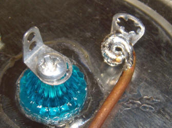 large tapered plastic necklace bead as described previously. The hole was
drilled small and then widened carefully with a tapered
large tapered plastic necklace bead as described previously. The hole was
drilled small and then widened carefully with a tapered
 reamer until the bead
almost rested on its shoulder when inserted. The metal around the hole was
heated with a soldering iron and the bead was pushed into the hole until the
shoulder itself started to melt a little. The plastic oozes into the splits in
the metal from the reaming process and becomes solidly anchored. These beads
have a hole large enough for a #4 bolt so two standoffs were mounted on each
side of the hole. The interior standoff holds a stiff piece of 14AWG copper wire
salvaged from a piece of Romex house wiring. The photo to the right shows the
internal copper wire soldered to one bent standoff and the outside
view of the other standoff. The bolt was eventually put in the other way because
of the difficulty in threading the nut onto the bolt down in the chamber. This
simple insulator is quite effective and seems to perform as well as exotic
Teflon standoffs. The only drawback could be the large amount of exposed plastic
that might accumulate a charge in some instances. The insulation properties are
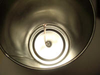
excellent and a thoroughly melted-in standoff is very strong. A piece of copper
PCB material was cut to fit well inside a mint can cover, and a center hole was
drilled to clear the plastic insulator. The PCB will be at zero volts potential
and the tin will be at a higher positive voltage, so it is important to make
sure the two don't touch. The mint can shown below was coated on the inside with
electrical tape (not shown) and the bottom, which is normally concave, was pressed out to
make the interior of the can larger. The rounded end of the red handle of a
large X-Acto knife makes a good tool for pressing the metal out. Remove the
blade first! Two notches are eventually cut for the wires and access to the
zeroing potentiometer. The PCB material was secured in place with spray
adhesive. The circuit is built directly onto the copper board using
point-to-point wiring.
reamer until the bead
almost rested on its shoulder when inserted. The metal around the hole was
heated with a soldering iron and the bead was pushed into the hole until the
shoulder itself started to melt a little. The plastic oozes into the splits in
the metal from the reaming process and becomes solidly anchored. These beads
have a hole large enough for a #4 bolt so two standoffs were mounted on each
side of the hole. The interior standoff holds a stiff piece of 14AWG copper wire
salvaged from a piece of Romex house wiring. The photo to the right shows the
internal copper wire soldered to one bent standoff and the outside
view of the other standoff. The bolt was eventually put in the other way because
of the difficulty in threading the nut onto the bolt down in the chamber. This
simple insulator is quite effective and seems to perform as well as exotic
Teflon standoffs. The only drawback could be the large amount of exposed plastic
that might accumulate a charge in some instances. The insulation properties are
excellent and a thoroughly melted-in standoff is very strong. A piece of copper
PCB material was cut to fit well inside a mint can cover, and a center hole was
drilled to clear the plastic insulator. The PCB will be at zero volts potential
and the tin will be at a higher positive voltage, so it is important to make
sure the two don't touch. The mint can shown below was coated on the inside with
electrical tape (not shown) and the bottom, which is normally concave, was pressed out to
make the interior of the can larger. The rounded end of the red handle of a
large X-Acto knife makes a good tool for pressing the metal out. Remove the
blade first! Two notches are eventually cut for the wires and access to the
zeroing potentiometer. The PCB material was secured in place with spray
adhesive. The circuit is built directly onto the copper board using
point-to-point wiring.
 The large glass resistor is held in position by two more necklace beads, the
new insulator of choice in the lab. The beads were partially melted by holding a
soldering iron tip in the hole for a minute or so, taking care
not to touch the plastic. While the plastic was still soft, the bead was pressed
onto the resistor. The beads were melted onto the PCB by heating the PCB with
the soldering iron and a little solder while gently pressing the bead down. This
connection isn't particularly strong, and a little plastic glue was added to the
now-flat side of the beads when they came loose. Keep the resistor clean and
free of fingerprints, and make sure the wire from the insulator to the resistor
doesn't touch anything. Construction is crowded simply to allow for more
circuitry in the future.
The large glass resistor is held in position by two more necklace beads, the
new insulator of choice in the lab. The beads were partially melted by holding a
soldering iron tip in the hole for a minute or so, taking care
not to touch the plastic. While the plastic was still soft, the bead was pressed
onto the resistor. The beads were melted onto the PCB by heating the PCB with
the soldering iron and a little solder while gently pressing the bead down. This
connection isn't particularly strong, and a little plastic glue was added to the
now-flat side of the beads when they came loose. Keep the resistor clean and
free of fingerprints, and make sure the wire from the insulator to the resistor
doesn't touch anything. Construction is crowded simply to allow for more
circuitry in the future.
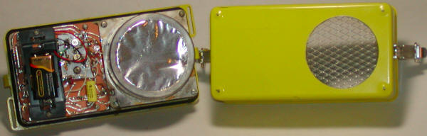
The cans were painted yellow, but provisions must be made to make good electrical contact between the chamber can and the end cap which can be aluminum foil, wire screen, etc. The prototype has a short length of tinned copper shield braid soldered to the inside of the can and folded over the lip of the opening:
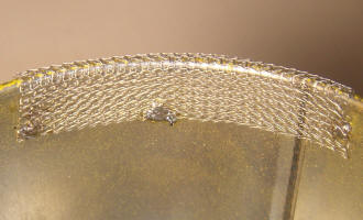
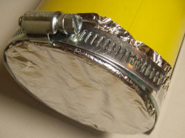
A single piece of bare copper wire would also work. An ordinary pipe clamp is used to secure the foil or screen but a rubber-band would also suffice. The clamping action forces the foil or screen against the grounding conductor. Alternatively, the paint could be removed from the end of the can.
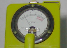
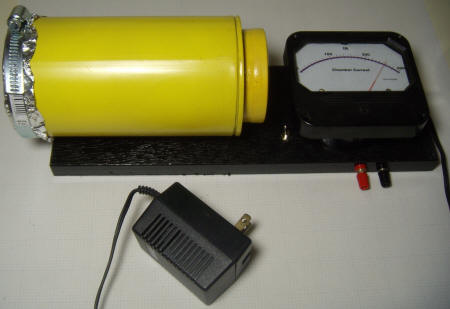
The actual unit deviates from the schematic somewhat and the finishing touches evolved. Firstly, the digital meter was replaced with an analog current meter with a custom face. In order to achieve good sensitivity, a range switch was added as were connections for an external meter or computer data taker. For "normal" sensitivity, a 3k resistor is connected in series with the meter (3 volts gives a full scale current of 1 mA). The toggle switch connects a 220 ohm across the 3k to give a total resistance near 300 ohms (adding the meter's resistance) for a X10 scale. The large meter was mounted directly to the top of a box that once held a pair of calipers by its electrical terminals instead of mounting it in the conventional manner. The chamber was mounted to the box with a couple of sheet metal screws screwed right into the sides of the chamber.
So far, these are pretty ordinary modifications, but now the project deviates from "normal engineering practices". In order to get a very long averaging time for the meter, a 1 farad super capacitor was connected across the terminals of the meter. This unorthodox technique actually works pretty well. The meter resistance is about 100 ohms so the time constant is about 100 seconds. By keeping the resistance across the super cap low, any problems associated with dielectric adsorption, etc. are minimized. Another RC was added for an analog voltage output (the two banana plugs at the top of the photo above). The capacitor is 0.22 farad and the series resistor is 500 ohms (two 1k resistors in parallel). The capacitor has two 5 volt zeners head-to-head across it to prevent over-voltage which will quickly damage a super capacitor.
The power supply is a bit of an after-thought to avoid batteries. The two black wires come from an unregulated molded "wall-wart" power supply that supplies about 20 volts. A 390 ohm resistor and 9 volt zener form a 9 volt supply to run the op-amp and a 10k resistor, and a 16 volt zener provide 16 volts to bias the chamber. The modified schematic is shown below:
Not shown in the schematic is a last-minute power indicator LED added in series with the 390 ohm resistor. If the circuit will not zero on the sensitive scale, the 9 volt power supply is changing voltage too much (due to the extra current required to charge the super caps). In that case, switch to a three-terminal regulator and set the ion chamber voltage a little lower to assure the regulator has enough voltage drop across it. A 100 uA meter movement will also eliminate the problem, allowing the meter resistors to be raised by a factor of 10, from 3 k to 30 k and 220 ohm to 3 k.
The ionization chamber works about as well as can be expected without significantly more care in chamber design. The long averaging time makes it possible to see radiation from very weak sources. Below is a plot of the response when a radioactive lantern mantle is rested up against the foil window then removed five minutes later:
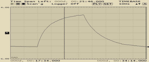
The long super cap time constant is clearly seen and the absence of noise is refreshing. Such extra-long averaging times would be useful for testing samples slipped directly inside the chamber, too, but the casual experimenter may wish to shorten the response time a bit by choosing lower value caps. Although the schematic doesn't show it, a double-pole switch was eventually added to disconnect one leg of each super capacitor for those times when a fast response is desired. Also, keep in mind that the circuit will take a long time to settle after power is first applied and much longer when the super caps are used. The meter will peg for several minutes and adjusting the zero with the caps switched in can be tricky since it takes many minutes to see the results of an adjustment. With experience, the speed of the drifting can allow the zero to be set with the caps connected. Simply try to stop the meter. Then very, very slowly adjust the needle to a low reading, perhaps 20% of full-scale. Expect to be "lost" once or twice with such a long time constant!
Other Ideas
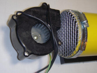 Using
a wire mesh instead of aluminum foil for the window allows alpha and beta
particles to enter the chamber more easily. The mesh also allows air to be blown
into the chamber with an induction motor or brushless motor fan. (Brush motors
will probably generate too many ions of their own.) The photo shows a fan
positioned off to one side to create a bit of airflow through the chamber. This
arrangement blows ions in the surrounding air into the chamber where they are
separated by the chamber potential, producing an upward meter deflection.
Lighting a match or butane lighter anywhere near the fan's input pegs the meter.
Alpha emitters such as the element from a smoke detector or a lantern mantle
give very high readings if held nearby. Turning the fan on and off might provide
some idea about the level of ionization in the room, but leaving the fan on and
blocking the air with cardboard might give more consistent results since the
electric and magnetic fields from the motor may influence the reading. The
basement lab where this technique was tried showed a consistent 100 mV increase
with airflow (the super caps and computer plotter were indispensable for the
measurement). Perhaps a radon test is in order!
Using
a wire mesh instead of aluminum foil for the window allows alpha and beta
particles to enter the chamber more easily. The mesh also allows air to be blown
into the chamber with an induction motor or brushless motor fan. (Brush motors
will probably generate too many ions of their own.) The photo shows a fan
positioned off to one side to create a bit of airflow through the chamber. This
arrangement blows ions in the surrounding air into the chamber where they are
separated by the chamber potential, producing an upward meter deflection.
Lighting a match or butane lighter anywhere near the fan's input pegs the meter.
Alpha emitters such as the element from a smoke detector or a lantern mantle
give very high readings if held nearby. Turning the fan on and off might provide
some idea about the level of ionization in the room, but leaving the fan on and
blocking the air with cardboard might give more consistent results since the
electric and magnetic fields from the motor may influence the reading. The
basement lab where this technique was tried showed a consistent 100 mV increase
with airflow (the super caps and computer plotter were indispensable for the
measurement). Perhaps a radon test is in order!
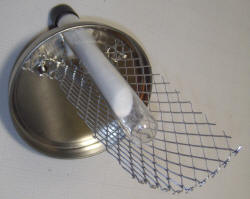
A wire tray was built onto the original lid and a hole was cut so that items could be inserted into the chamber right above the center wire without opening the chamber. Power should be removed when installing or removing the tray to prevent shorting the outer can to the center wire. The tray is useful for observing the radiation from long objects like thoriated tungsten electrodes or test tubes filled with radioactive substances. If a coarse mesh is used the circuit will respond to the slight change in electric field when an item is inserted, so some settling time will be required. Experience has shown that observing the change when the item is removed instead of inserted gives better results. Heavy items will cause the tray to bend toward the wire slightly, so it is best to flip the lid 180 degrees so that the inserted item rests on the bottom of the can with the screen above. If the chamber is mounted with sheet metal screws through the bottom as with this prototype, twist the lid slightly so that inserted items miss the screws. An open paper tray allows the observation of radiation from alpha and beta emitters. The tray in the photo below is made from thin cardboard and is filled with potassium chloride, a beta emitter. The low level of radiation is just detectable using the long averaging and a computer plot, giving about a 20 mV change.
Fairly weak sources can be measured with the wire mesh in place. A thick piece of pink granite was found to give a Geiger-counter reading about 60% higher than the background reading using a long averaging time. The slab gives a noticeable reading increase when placed in front of the ion chamber as shown below. The chart starts with a "hot" part of the slab in front of the chamber, then the slab is removed, and lastly, the slab is replaced but with a less radioactive portion in front of the chamber.
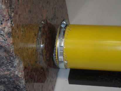
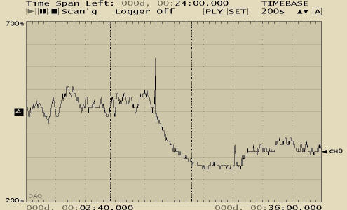
The two large spikes are from the vibration produced when moving the slab; it is heavy! The voltage change from the high reading to background level is about 160 mV. With these long averaging times, the chamber performs well, even when compared to a large tube Geiger-counter. (The chart runs for 30 minutes.)
![]()