Modest power audio amplifiers for driving small speakers or other light loads can be constructed in a number of ways. The first choice is usually an integrated circuit designed for the purpose such as the LM386 or newer class D switching types that often accept digital data instead of simple audio voltage. Discrete designs can also be built with readily available transistors or op-amps and many designs are featured in manufacturers' application notes. Older designs employed audio interstage and output transformers but the cost and size of these parts has made them all but disappear. Here are a few easy-to-build analog audio amplifier circuits for a variety of hobby applications:
This simple amplifier shows the LM386 in a high-gain configuration (A = 200). For a maximum gain of only 20, leave out the 10 uF connected from pin 1 to pin 8. Maximum gains between 20 and 200 may be realized by adding a selected resistor in series with the same 10 uF capacitor. The 10k potentiometer will give the amplifier a variable gain from zero up to that maximum.
I've moved this circuit to Area 50 as it's a bit experimental.
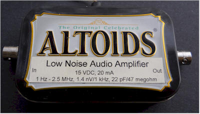
The Curiously Low Noise Amplifier takes advantage of the wonderful noise characteristics of the 2SK117 JFET that boasts a noise voltage below 1 nV/root-Hz and virtually no noise current. The noise voltage of the amplifier is only 1.4 nV/root-Hz at 1 kHz, increasing to only 2.7 nV/root-Hz at 10 Hz. The noise current is difficult to measure, so this simple utility amplifier can see the noise from a 50 ohm resistor and a 100k resistor, too. (The 1.4 nV input-referred noise will increase to about 1.7 nV with a 50 ohm resistor, instead of a short, and a 100k resistor will give an input-referred noise near 40 nV, with very little contribution from the amplifier.)
This amplifier is a "utility" amplifier with a gain of 100, that would typically be used in a lab setting to boost tiny signals for measurement or further processing. It isn't intended to drive a speaker or headphones directly. (It could drive the LM386 quite nicely.) The circuit is a simple discrete transistor feedback circuit with two gain stages and a unique class-A output buffer:

The 2sk117 is from the "BL" Idss current range and is selected for an Idss near 7 mA. The drain resistor is adjusted to achieve about 4 volts on the drain and the value depends on the Idss of the JFET.
Most of the resistors aren't critical, but precision values are shown because the resistors should be metal film types for best noise performance. Approximate DC voltages are shown for helping with resistor selection. Deviating from the shown voltages will reduce the available output voltage swing, but the amplifier might work fine for smaller signals. Unloaded swing should be about 6 volts, p-p with about 60 mV p-p input, before distortion is observed.
The MPSA18 acts as a noise filter. High gain is desirable here to keep the value of the base filter capacitor reasonable, but a 2N4401 could be substituted by reducing the 10k and 120k by a factor of 5. The filter will still be rolling off the noise voltage from the 15 volts supply above about 0.2 Hz. But some power supplies can be really noisy!
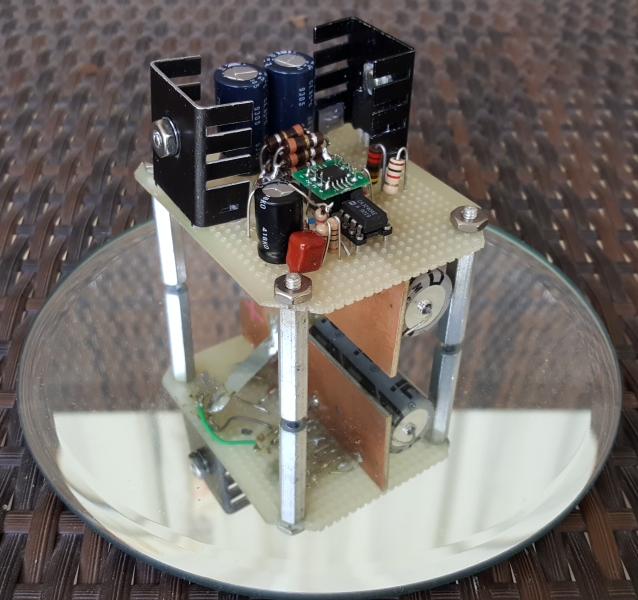
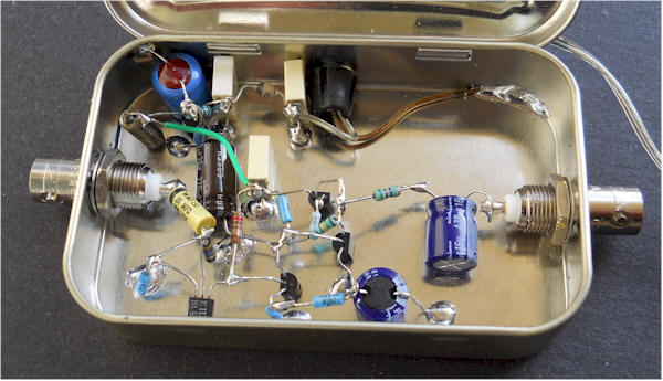
The 0.1 uF capacitors serve as bypass capacitors but mainly as terminals for holding the components. These are the white rectangles seen in the photo.
The feedback resistor is selected for a gain of exactly 100 and the value is well above the expected 1k, due to the limited open-loop gain of the simple circuit.
A small resistor is included in series with the output for stability and that resistor can reduce the gain a bit when driving a lower resistance load. The designer may choose to set the gain for that particular load, say 75 ohms, or for a high impedance load. The circuit can drive a lower resistance than 100 ohms, but the swing will be somewhat limited. It may be possible to leave out the 33 ohm resistor without stability issues. (Usually, such a utility amplifier is driving a much higher resistance load, typically 600 ohms or above.) Note: To give you an idea of how you can play with the output resistance, I just changed my unit's series output resistor to 55 ohms and adjusted the gain for 35 dB when driving 75 ohm loads. Unloaded the gain is exactly 5 dB higher at 40 dB. This way I have even number gains whether driving a 75 ohm instrument or a high-Z device. The output buffer has no trouble driving the total 125 ohm load, with a swing limit of about 3.5 volts, p-p.
The output stage is an unusual self-biasing arrangement where the PNP holds the gate-source voltage near 0.6 volts, running the JFET somewhat below its Idss. The 2N5486 was chosen to not waste too much current, but a higher Idss JFET will give more drive capability, if desired.
Input Impedance: 47 megohm (set by bias resistor), shunted by 20 pF
Output Impedance: 36 ohms, set by series resistor plus about 3 ohms from the circuit. My 55 ohm resistor mentioned above gives an output Z of about 58 ohms and exactly 5 dB of gain loss from no load to 75 ohms.
Output voltage swing: 6 volts p-p into a high impedance load.
Gain: 100 (40 dB) set by feedback resistor. Lower gain could be selected for wider bandwidth.
Frequency Response: flat from below 1 Hz to above 2 MHz.
Input Noise: 1.4 nV, rising to 2.7 nV at 10 Hz. Noise current has eluded measurement so far, but it's really low. With a 97.3 k resistor (100k in parallel with 3.6 meg) connected across the input, the noise voltage measures within a tiny fraction of a dB of 40 nV, so little to no noise current is seen. In fact, this amp and a selected resistor make an inherently accurate noise source. Connect a 152k across the input (in a shielded box), and you have a precise 5 uV/root-Hz noise source throughout the audio spectrum (50 nV times 100). A quick measurement at 40 Hz gives 770 nV/root-Hz with nothing connected; the 47 megohm is expected to contribute 867 nV. That's pretty close and still little noise current from the FET.
For even better performance, the bipolar stages could be replaced with a low noise op-amp. The input noise would drop a little, perhaps to 1 nV, as would the input capacitance, perhaps below 10 pf. Compensating the op-amp might be a bit of a challenge.
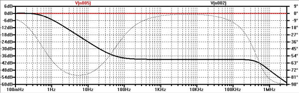
Here's another version with some interesting features. There's a two-transistor "brute-force" noise shunt that cleans up the power supply quite effectively and it will work well with a series resistor as low as 1 ohm. But the required DC current goes up if there's lots of noise to shunt. As with the "finesse" circuit, it's only good for removing random noise, say from a three-terminal regulator, and will be overloaded by large spurs or hum. Here's what it does to a test source (red) inserted in series with the power supply:
Use high-gain transistors for best results. Ordinary transistors will give about 30 dB of rejection but the bias resistor values may need to be modified to increase the current back up to around 30 mA, depending on how much noise needs to be shunted. The circuit has an excellent noise floor so start with a good supply and the noise will be in the single-digit nanovolts. (Spice thinks less than 1!)
For a special application needing minimal loading, the amplifier includes feedback to bootstrap the input capacitance to a low value (about 4 pF). That technique combined with the source feedback usually leads to terrible ringing for some source impedance but this amplifier has only 1dB of peaking at the worst value (around 30k). Run the LTSpice simulation to see the response curves for various values of input R (change the list as desired). Right-click on the .step param command to comment it out and change {R} to a fixed value, say 1 ohm, for testing the amp at a single source impedance. The noise is just below 1 nV/root-hertz. This amplifier works up to the bottom of the BCB for source impedance as high as 30k. This is just a spice implementation at this point - stay tuned.
Note: I connected the top of the 220 ohm resistor directly to the power source to reduce the drop across the 4.7 ohm resistor. If the extra drop is not a problem the circuit works slightly better with the top of the 220 ohm connected to the right side of the 4.7 ohm resistor.
When I say "supply can be terrible if this circuit is used" I mean in terms of random noise, say from an LM7815 three-terminal regulator (hundreds of nV/root-Hz). This noise shunt can't handle unregulated sources or lots of huge spikes on the power. Whatever noise is present will generate current in the small resistor (assuming the circuit is working) and the circuit needs to be able to shunt that current. With 30 mA bias the circuit can handle about +- 25 mA signals so the above circuit with the 4.7 ohm resistor can handle just under 250 mV p-p. Drop the resistor to 1 ohm and the limit is more like 50 mV p-p, well within expectations for a three-terminal regulator but not capable of removing much ripple or large transients.
Here's a 1uV/root-Hz noise voltage source that will drive a 50 ohm load from below 10 Hz to over 500 kHz. The noise shunt actually stabilizes the circuit against battery resistance, a common feedback path in such simple circuits. Current consumption is under 20 mA.
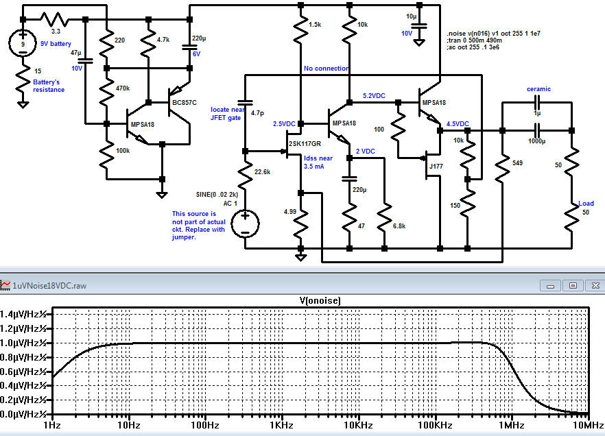
Note: I connected the top of the 220 ohm resistor directly to the power source to reduce the drop across the 3.3 ohm resistor. If the extra drop is not a problem the circuit works slightly better with the top of the 220 ohm connected to the right side of the 4.7 ohm resistor.
Here is a simple amplifier for boosting the audio level from low-power sound cards or other audio sources driving small speakers like toys or small transistor radios. The circuit will deliver about 2 watts as shown. The parts are not critical and substitutions will usually work. The two 2.2 ohm resistors may be replaced with one 3.9 ohm resistor in either emitter.
The circuit above shows a 4-transistor utility amplifier suitable for a variety of projects including receivers, intercoms, microphones, telephone pick-up coils, and general audio monitoring. The amplifier has a power isolation circuit and bandwidth limiting to reduce oscillations and "motorboating". The values are not particularly critical and modest deviations from the indicated values will not significantly degrade the performance.
Three cell battery packs giving about 4.5 volts are recommended for most transformerless audio amplifiers driving small 8 ohm speakers. The battery life will be considerably longer than a 9 volt rectangular battery and the cell resistance will remain lower over the life of the battery resulting in less distortion and stability problems.
The amplifier may be modified to work with a 9 volt battery if desired by moving the output transistors' bias point. Lowering the 33k resistor connected from the second transistor's base to ground to about 10k will move the voltage on the output electrolytic capacitor to about 1/2 the supply voltage. This bias change gives more signal swing before clipping occurs and this change is not necessary if the volume is adequate.
As before, the two 4.7 ohm resistors may be replaced with a single 10 ohm resistor in series with either emitter.
The above circuit is a versatile audio amplifier employing a low cost LM358 op-amp. The differential inputs give the amplifier excellent immunity to common-mode signals which are a common cause of amplifier instability. The dotted ground connection represents the wiring in a typical project illustrating how the ground sensing input can be connected to the ground at the source of the audio instead of at the amplifier where high currents are present. If the source is a power supply referenced signal then one of the amplifier inputs is connected to the positive supply. For example, an NPN common-emitter preamplifier may be added for very high gain and by connecting the differential inputs across the collector resistor instead of from collector to ground, destabilizing feedback via the power supply is greatly reduced. By the way, the LM358 is a fairly poor audio amplifier and you may wish to switch to a better part for reduced distortion. Frankly, for a little bench amplifier, you'll never notice the distortion.
|
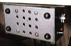
My utility amplifier was built into an aluminum Bud box and eventually ended up bolted to the bottom of a shelf as shown. The well-behaved and ready-to-go amplifier is really handy. |
| Here is the amplifier used to boost the output from a simple crystal radio. The volume control is at the bottom left and the other components are on the terminal strip at the bottom of the picture. This is a really quick and easy audio amplifier! | 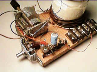 |
A class-A audio amplifier is pretty wasteful of power but when plenty of power is available the simplicity is attractive. Here is a simple darlington transistor example intended for use with a 5 volt power supply:
This circuit and the following aren't for beginners; they are of limited usefulness and require an understanding of the underlying principles and potential applications. They all pass DC through the speaker which is wasteful and can cause problems for the inexperienced builder. If built without variation, they should perform as described but make sure to read the text.
The 5 volts should be provided by a regulated power supply. The efficiency is below 25% and significant DC current flows in the speaker and that additional power should be figured in to the power rating of the speaker. But look how simple it is! The voltage gain is only about 20 and the input impedance is about 12k. The schematic shows two values of bias resistor to be used with the corresponding speaker impedance. With the 150k bias resistor and 8 ohm speaker, the circuit draws about 210mA (1 watt) and can deliver about 250 mW to the speaker which is plenty of volume for most small projects. The speaker should be rated at 500 mW or more and should exhibit a DC resistance near 8 ohms (perhaps 7 ohms). Check the candidate speaker with an ohmmeter; much below 7 ohms will cause excessive current draw. With the 220k resistor and 16 ohm speaker, the circuit draws about 100 mA (500 mW) and delivers about 125 mW to the speaker. The 16 ohms speaker should be rated at 200 mW or more and exhibit nearly 16 ohms of DC resistance. (Most small speakers have a DC resistance near the rated impedance and that resistance is used to set the quiescent current level in this circuit.) Other NPN darlington transistors will work but choose one that can dissipate 1 watt minimum. Most power types don't need a heatsink but tiny TO92's might overheat.
If the inefficiency of the class-A hasn't dissuaded you yet, here is a 4-transistor amplifier suitable for small signals:
The input impedance is about 5000 ohms and the frequency response is flat from 30 Hz to over 20,000 Hz. With the 8 ohm speaker the current drain is about 215 mA and the gain is about 1700 (64 dB). With the 16 ohm speaker the current gain is about 110 mA and the gain is about 2500 (68 dB). A volume control may be added by connecting one end of a 5k potentiometer to ground, the wiper to the amplifier input. The other end of the pot becomes the input.
Lets face it; just about any of the various IC audio amplifiers make more sense than this inefficient design. But, this circuit uses parts with only 3 legs. Umm, it doesn't use large capacitors except for the power supply bypassing. Lets see, its more fun-ariffic. Well, lets see if we can come up with a project that takes advantage of the inefficiency:
So, what is it?
It is a modulated light sender! Connect the input to an audio source or microphone (a speaker will work) and the audio will amplitude modulate the light intensity. The inefficiency of the class-A works in our favor now, lighting the lamp to mid-brightness with no audio present. Actually, with a 4.7 volt bulb, the lamp will be near full brightness and will be "overdriven" on sound peaks. A higher voltage bulb will last longer but will be dimmer. Try a 6.8 volt bulb as a compromise. With a sensitive detector like a phototransistor, this communicator will work several hundred feet (at night). Best range is realized if the bulb is mounted in a typical flashlight reflector and the detector is similarly mounted. The input capacitor is reduced to .01 uF to give the amplifier a high-pass character to compensate for the slow response of the bulb. The audio will sound a bit muffled, anyway. The clever designer could use this amplifier for the receiver, too, switching the speaker to the input for transmitting and to the output for listening. If you choose a detector with good infrared response, like a pin photo diode, you can add plastic IR filters to block out ambient light and make the communicator harder to see at night.
Increasing the voltage to 12 VDC, replacing the bulb with a 3 watt, 16 ohm speaker and replacing the .01uF with a 1uF gives an audio amp that will deliver nearly 1 watt of audio power. The speaker will get warm, however! (Due to the nearly 2 watts of DC power in the speaker coil.)