Also see a version that uses an IC instead of an old keyboard.
A "keyboard wedge" is a device for connecting between a keyboard and computer for automatically entering information, as though it were typed, avoiding the need for a special program to be running on the computer. The Keyboard Wedgie is a lightweight version for entering binary data into a spreadsheet or other program. It uses a small PicAXE processor to measure a voltage with 10 bits resolution and enter that value, in binary, into a desktop computer, typically into a spreadsheet program. It replaces either an old serial keyboard or a USB keyboard and will work with another keyboard attached, in most cases. This abbreviated device can only punch three keys, the "0," "1," and "enter" keys, just enough to enter a binary value into sequential cells in a spreadsheet or lines in a text editor. Since the Keyboard Wedgie simulates key presses, it will work with just about any keyboard system without any knowledge of the signaling protocols. It, after all, just presses buttons.
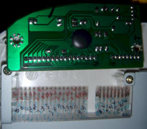
Typically, the experimenter will choose to modify an older ps-2 keyboard, but the idea will work with just about any type, as long as a 5 volt power source is available to run the PicAXE. Here's the view inside a typical keyboard:
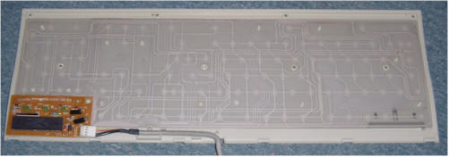
Below is a view of a more modern PCB, unplugged from the keyboard membranes. Notice how I marked the board and membrane edge connectors for reference. The key switches are connected to a matrix of "rows and columns" and the big IC determines which key is pressed by shorting one "column" after the other to ground and looking for any "row" that becomes shorted, as a result. ("Rows" and "columns" are in quotes because they aren't necessarily arranged that way on the keyboard.) Typically, little pads on one membrane make connection with corresponding pads on the other, when a key is pressed. Therefore, the rows and columns are separated into two sets, one with the conductors on top of one membrane, and one with the conductors on the bottom of the other membrane. The first task is to determine which pin from one set gets shorted to which pin from the other set for the "0." "1," and "enter" keys.
|
|
Key | PCB Pins | CD4016 switch pins |
PicAXE control pins |
| 0 | 5, I | 10, 11 | out0 "0" | |
| 1 | 5, P | 9, 8 | out1 "1" | |
| Enter | 2, L | 3, 4 | out2 "enter" |
The chart to the right of the picture shows what I discovered and the choices I made. I just used the alphabet for one set of pins and numbers for the other (the shorter row of contacts). Your results will be different and you can use any of the four analog switches in the CD4016. I found the two pins that need to be shorted for each key by touching the Curious C-Beeper to the exposed conductors on the membranes and repeatedly pressing the desired key. The capacitance change makes the tone from the C-Beeper go up and down, like a British police car's siren, due to the extra capacitance caused by connecting the two membrane traces. An ohmmeter will also work but might require a bit more dexterity to push the button and test both sets of conductors for continuity. You can successfully trace them out visually, too.
| Don't have a CD4016 handy? Here's another
way: The featured design uses a
common analog switch, the CD4016, to make the desired
connections but other switching devices may be used, including
various solid-state and mechanical relays and FET transistors. Using
a single transistor like the BS170 or 2N7000 requires knowing which
connection is the most positive. The "row" lines on older
keyboards often have a visible pull-up resistor network (a
black SIP near the big IC) and the IC pulls each "column" lines to ground in a
rapid succession. The rows with the pull-ups
are always the most positive and the drains of the switch FETs should
connect there. The sources of those FETs will connect to the desired columns for a
particular key, one FET per key. Newer keyboards have the pull-ups
integral to an IC that looks like a blob of epoxy on the back of the
PCB and it becomes more difficult to determine how to connect the
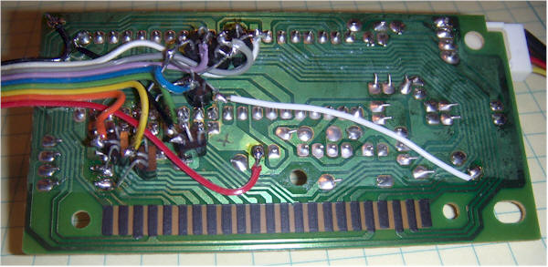
FETs. Here's the backside of the PCB from an early prototype using
FETs to push seven keys. (I thought I would want the four arrow keys
but never used them.) This is the back side of the older PCB shown
in the first keyboard photo above: This is just informational. The CD4016 is less error-prone. |
Once you know which pins need to be shorted for the three keys, attach wires to those pins. I only needed two wires on one side of the board because the two number keys share a common trace. I recommend using the number keys at the top of the keyboard and not the keypad to avoid "numlock" issues.
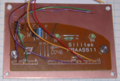
As soon as you connect those wires, you can plug the little board into the computer and try shorting the various wires together to see if you get the right response. In my case, I can short the green wire to the violet or orange wire to get a "0" or "1" and the violet wire on the left to the red wire to get an "enter."
Note: Newer computers don't seem to mind if you plug and unplug a keyboard while the computer is running. I don't know if I can recommend it; old computers would sometimes crash and even be damaged. I've done it many times on a fairly new computer with no problem. You decide for yourself! Also, I have had no problem running a USB keyboard alongside this thing so I can still type while it's connected. I suspect two USB keyboards will work, too. In fact, this gadget could be USB and the "real" keyboard could be an older PS-2 type. Make sure you have 5 volts available on the PCB. I picked it off at the obvious filter cap.
The keyboard PCB was mounted to a project case cover in the above photo. Below, the additional circuitry is mounted above the PCB on a piece of perfboard. The analog input comes in the banana plugs and the trigger pulse comes in via the RCA connector.
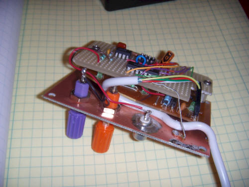
The op-amp is a single-supply type rated for "rail-to-rail" inputs and outputs. The first op-amp has a gain near 5, giving a full-scale range of about 1 volt. A 22 megohm and 0.1 uF give the input a low-pass characteristic, since the sampling will be slow. 10 megohms will work in place of the 22 megohms. The second op-amp simply buffers the signal that triggers the measurement. In the schematic, two, 40.2 k resistors bias pin 6 to 2.5 volts, but it may be desirable to change that threshold by changing one of the resistors. For example, my final configuration uses the changing voltage across the Scroll Lock LED to trigger a measurement, as explained below. That voltage was measured to change from 5 volts to about 3 volts (a single LED voltage drop). So, I changed the 40.2 k resistor between pin 6 and +5 volts to a 10 k resistor, biasing pin 6 up to about 4 volts, which is right in the middle. Debounce hysteresis isn't necessary.
The PicAXE wiring is straightforward. Pin 2 should be grounded and I used a 22k, in case I might want to program it in place (not likely, it turns out). The op-amp provides the low impedance drive that is recommended for pin 3 (the analog input). +5 VDC and Ground can be found on the keyboard PCB and are usually obvious. My keyboard was actually labeled with silkscreened text.
The key wiring connects to the two wires that need to be shorted together to send the indicated character. The polarity doesn't matter and it's likely that the two number keys will share a wire.
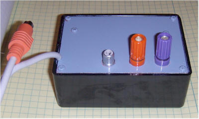
The original finished unit is shown above. Eventually, the RCA connector was removed and replaced with a panel-mount LED connected to the keyboard's Scroll Lock LED pads (after removing the original tiny one). The negative LED leg was connected to the trigger input. That connection allows a Windows program to trigger a measurement by flashing the Scroll Lock LED. If you would rather have the measurement triggered externally, with no special software on the PC, leave the RCA connector and apply a trigger pulse no faster than about once per 5 seconds (or much slower, if desired). The PicAXE program is tolerant of just about any pulse width except very, very short pulses that might be missed.
Below is the entire PicAXE program. Just cut and paste the text into the PicAXE editor (with the 08M selected under options). Click on "syntax" and it should pass, showing a generous 92 bytes to spare. Plug a 08M PicAXE (little 8-pin version) into the socket and hit "program." That's really all it takes.
symbol ReadingA = w0 'variable w0
(two bytes) is called ReadingA, uses b1 and b0 and is from ADC 4 (input 4).
symbol Trig = b2 'variable bit5 is called Trig and will be set high when the
"trigger a measurement" input occurs.
main:
let dirs = %00000111 ' sets pins 7,6 and 5 to outputs (Out0, Out1, and Out2)
for b4 = 1 to 1000 'the program stops after 1000 data points. Feel free to
change.
trigger:
let Trig = pins and 8'reads input 3 (pin 4) and sets Trig. And 8 picks off pin 4
(input 3) and ignores the others.
If Trig = 0 then trigger 'wait for Trig to go high before proceeding.
waitforlow:
let Trig = pins and 8'reads input 3 (pin 4) and sets Trig. And 8 picks off pin 4
(input 3) and ignores the others.
If Trig = 8 then waitforlow 'wait for Trig to go low before reading a data
point. These two loops allow for any pulse width or polarity to work.
datataker:
READADC10 4,ReadingA 'reads ADC 4 with 10 bits resolution
If bit9 = 0 Then high 0: else high 1: endif 'these punch "1" or "0" buttons for
each bit (output 4 is "0" and 5 is "1")
gosub upkeys
If bit8 = 0 Then high 0: else high 1: endif 'pins 0 and 1 were intentionally
chosen to push "0" and "1" keys but other assignments would work.
gosub upkeys
If bit7 = 0 Then high 0: else high 1: endif
gosub upkeys
If bit6 = 0 Then high 0: else high 1: endif
gosub upkeys
If bit5 = 0 Then high 0: else high 1: endif
gosub upkeys
If bit4 = 0 Then high 0: else high 1: endif
gosub upkeys
If bit3 = 0 Then high 0: else high 1: endif
gosub upkeys
If bit2 = 0 Then high 0: else high 1: endif
gosub upkeys
If bit1 = 0 Then high 0: else high 1: endif
gosub upkeys
If bit0 = 0 Then high 0: else high 1: endif
gosub upkeys
high 2: pause 200: low 2 'enter key (ran out of gosubs so upkey is here, too.)
next b4
end
upkeys:
pause 100
let pins = %00000000
pause 150
return 'this subroutine delays a short time and resets all keys to "not
pressed."
A simple program may be written to flash the Scroll Lock LED every minute using AutoHotkey (www.autohotkey.com). Here's the simple script:
;
; AutoHotkey Version: 1.x
; Language: English
; Platform: Win9x/NT
; Author: CWenzel <charles@wenzel.com>
;
; Script Function:
; Blinks ScrollLock every minute for 2 seconds at the half-minute. (Used to
trigger Keyboard Wedgie data taker.)
; Add more IfEqual statements in pairs for more samples per minute.
;
#NoEnv ; Recommended for performance and compatibility with future AutoHotkey
releases.
SendMode Input ; Recommended for new scripts due to its superior speed and
reliability.
SetWorkingDir %A_ScriptDir% ; Ensures a consistent starting directory.
ScrollLockBlink:
IfEqual,A_Sec,30,SetScrollLockState, on
IfEqual,A_Sec,32,SetScrollLockState, off
Sleep, 1000
Goto, ScrollLockBlink
The part that I wrote is in red. It basically looks at a variable called A_Sec, which contains the number of seconds in the current minute, and turns the LED on when it's at the half-minute point. Two seconds later, it turns it off. I put the sleep for a second command in there out of ignorance, figuring it might lower the burden on the CPU. I can't see any CPU burden from this little script!
If you trust strangers with websites, here's a compiled .exe of the above script. It's safe, of course. But then, that's what they all say!
If you have more caution than that, you can download AutoHotkey and run this script or create your own .exe from this listing. Or, learn the simple scripting language and write a fancier version.
I should mention that I got the idea to use a script like this from the website, http://www.rjlsoftware.com/. Among more serious offerings, he offers "gag" software, one of which flashes the keyboard LEDs. I came across his site when trying to find a way to flash those LEDs, since they're right there with the Pic.
I was going to use his free software when I discovered just how easy AutoHotkey is to use. My script is a little more "user friendly" in that it has an icon in the program tray that can be used to pause or exit the script - just right-click on the green icon. His gag program actually hides from the victim!
Using the Keyboard Wedgie is simple but takes a little practice. First, open the program you wish to use to collect the data. I would start with Notepad or Wordpad just to see it work. Click in the text area of the program so that the "typing" occurs there. That's the hardest part to remember. You have to click on the spot where you want the data to go or it will start typing 1's and 0's everywhere! Remember, it's easy to take the focus away from the spreadsheet if you are doing other things on the computer so don't forget to click on the desired cell again when you're done. Make sure to pause the pulses when trying to use the computer so that the data taker doesn't start typing right in the middle of what you're doing. The little scroll lock program is easily paused by right-clicking on the green icon in the bottom tray. It will turn red when it's paused. When you un-pause it remember to click in the desired spreadsheet cell again.
Eventually you will want to use the data. The data is 10 bits of binary so you will want to convert it to decimal using the appropriately named "decimal" function in a spreadsheet program.
The program is limited to 1000 points (see the program listing) and that will comfortably fit in one column of a spreadsheet. Just click on the top, left column and start the trigger pulses. You can graph the collected data using the graphing functions of the spreadsheet program. Here's a plot of the signal strength of a VLF transmitter in Maine made by plotting the DC voltage from a selective level meter tuned to 24 kHz:
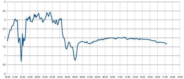
These signals are used by hobbyists to look for "Sudden Ionospheric Disturbances" or "SIDs" during the daylight hours. On the graph daylight is the smooth part off to the right. If there had been a solar flare that smooth curve would have a characteristic "glitch." This graph was made using a spreadsheet in openoffice.org.
Also see the Sid Seizer.
There are other uses for the Keyboard Wedgie. For example, a freeware program like IrfanView can be configured to do a screen capture when a function key is pressed. A very simple Keyboard Wedgie with only one switch could press that function key at an appropriate time, maybe to capture an image from a camera or a program's screen when an external event occurs. Or use AutoHotkey to program a function key to run a sophisticated script every time the Keyboard Wedgie presses a button.
The original experiment with the older keyboard was converted into a "deluxe" version:
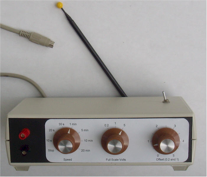
This project should have two nut symbols! It's pretty nutty. First of all, the reference frequency is obtained by receiving hum from the surrounding power wiring (See the CD4069 Atomic Frequency Standard.) The 60 cycle hum is divided down to one pulse per 10 seconds. Modifications for 50 Hz are described at the preceding link. Secondly, instead of interfacing with a computer in a conventional way, this thing electronically pushes the buttons on an old PC keyboard, eliminating the need for any special software on the PC. Prepare for ridicule from your more stodgy hobbyist friends. But you can always come up with a more conventional 10 second pulse and use the serial programming line to read the data, leaving out the analog switch and keyboard PCB. I find the keyboard function to be handy at times.
A larger PIC is used so that there are enough pins to read a binary-coded switch to select seven different sample times. The PIC program counts the required number of 10 second pulses to achieve the desired sampling rate. The input amplifier of this version features three sensitivities, and a DC offset pot that allows finer resolution measurements of signals with a large DC component on the two more sensitive scales. One of the analog switches is not used but is shown as being connected to the PIC. That switch could be used to press another key, if desired. For example, you could use a freeware program like IrfanView to capture a screen image when a function key is pressed. The PIC could finish a day's recording, press the function key, then start over. Or, the function key could do all sorts of other tasks, if programmed with Auto Hotkey. The PIC program as currently written saves 1,440 points then stops. That's 24 hours of 1 minute readings.
The input impedance is extremely high, so it's easy to add an external low-pass filter. Simply connect a capacitor across the input terminals and add a series resistor. A 1 uF, non-polar capacitor, combined with a 10 megohm will roll off above 16 millihertz. Even more is fine when long sampling intervals are used. Just make sure that the capacitor is a low leakage type. The circuit already has a 1 second time-constant filter that will roll off frequencies above about 0.15 Hz.
The details of the internal construction are not important since this unit evolved as opposed to being planned. The old keyboard PCB is mounted vertically, against a block of wood, the PIC and op-amp are mounted on an oddball prototyping board - a more traditional prototyping board would be fine, the 60 Hz receiver is potted in a box and bolted to the back panel, next to the antenna, and the divide-by-10 is hidden in a piece of blue heat shrink tubing. A "pause" switch was added to the top cover and a connector was added to the switch so that the top can be completely removed. An LED sticks out the back (hard to see in photo) for visual indication that the data taker is functioning. It can seem pretty dead when it's set for long delays.
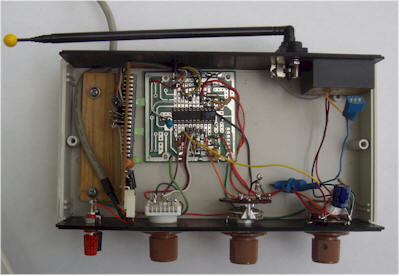
I don't recommend copying this layout!
A new listing is below (as of 1/25/2016). The new listing averages 64 readings and also outputs the value over the serial programming port in addition to the keyboard serial port. Paste it right into the PICAxe editor and click the Syntax button to verify. When you run the simulation, make sure to select the 14M IC. The program will oscillate between the first two lines, until you click on pin 6 (input 1). That's like turning the front knob from "stop" to "10 seconds". Then the program drops down to lines 27 thru 29, waiting for pulses from the reference. Click on pin 3 (input 4) a couple of times and the program will blink pin 9 (output 4), 10 times. If you want to see output 5 blink, too, set a value above zero into "A0" in the simulation control panel.
' Deluxe Keyboard Wedgie also with serial output.
This program is for the 14M IC
symbol ReadingA = w0 'variable w0 (two bytes) is called ReadingA and uses b1 and
b0 and is from ADC 0 (input 0).
symbol N = b4
symbol Total = w3
symbol Speed = b2 'variable b2 (one byte) is called Speed and will store 3 bits
from 8-position digital switch, inputs 1,2 and 3 (value from 2 to 14).
symbol Delay = b5 'used in for loop to set time between measurements.
symbol Trig = b3
main:
let Speed = pins AND 14 'reads three bits, 1,2,and 3.
If Speed = 0 then main 'Stops data taking and waits for Speed to be set to
greater than zero.
If Speed = 2 then let Delay = 1: endif '10 second delay
If Speed = 4 then let Delay = 2: endif '20 second delay
If Speed = 6 then let Delay = 3:endif '30 second delay
If Speed = 8 then let Delay = 6: endif '1 minute delay.
If Speed = 10 then let Delay = 30: endif '5 minutes
If Speed = 12 then let Delay = 60: endif '10 minutes
If Speed = 14 then let Delay = 120: endif '20 minutes
for N = 1 to Delay 'each pass is 10 seconds (10 second pulses from external
source are applied to pin 3 for this to work.)
high 3 'turn on optional activity LED so it is clear the thing is doing
something
trigger:
let Trig = pins and 16 'reads input 4 (pin 3 on 14M IC) and sets Trig.
If Trig = 0 then trigger 'wait for Trig to go high before proceeding.
low 3 'turn off activity LED
waitforlow:
let Trig = pins and 16'reads input 4 (pin 3) and sets Trig.
If Trig = 16 then waitforlow 'wait for Trig to go low before reading a data
point. These two loops allow for any pulse width or polarity to work.
next N
Total = 0
For N = 1 to 64 'Averages 64 readings.
READADC10 0,ReadingA 'reads ADC 0 with 10 bits resolution
Total = Total + ReadingA
Next N
ReadingA = Total/64 'ReadingA now has the average of 64 measurements
sertxd (#w0,13) 'sends reading and return out the programming serial port
If bit9 = 0 Then high 4: else high 5: endif 'these punch "1" or "0" buttons for
each bit (output 4 is "0" and 5 is "1")
gosub upkeys
If bit8 = 0 Then high 4: else high 5: endif
gosub upkeys
If bit7 = 0 Then high 4: else high 5: endif
gosub upkeys
If bit6 = 0 Then high 4: else high 5: endif
gosub upkeys
If bit5 = 0 Then high 4: else high 5: endif
gosub upkeys
If bit4 = 0 Then high 4: else high 5: endif
gosub upkeys
If bit3 = 0 Then high 4: else high 5: endif
gosub upkeys
If bit2 = 0 Then high 4: else high 5: endif
gosub upkeys
If bit1 = 0 Then high 4: else high 5: endif
gosub upkeys
If bit0 = 0 Then high 4: else high 5: endif
gosub upkeys
high 2: pause 200: low 2 'enter key
goto main
upkeys:
pause 150
let pins = %00000000
pause 150
return 'this subroutine delays a short time and resets all keys to "not
pressed."