
![]()
"Natural Radio" is simply radio noise with natural origins, mainly lightning, but also clouds of ions interacting with the earth's magnetic field. Nearby lightning sounds like the familiar crackle heard on an ordinary AM radio but distant lightning produces distinctive "chirps." The frequencies of the original pulse can be spread out in time (a process called "dispersion) because the higher frequencies travel a little faster than the lower. The result is that the short impulse from a lightning strike in South America can sound like a chirp in Texas. Slower sweeping tones are called "whistlers" and they are a bit of a mystery. Allyson's explanation is the best I've heard. When conditions are just right, numerous lightning strikes combine with numerous reflections to give an eerie chorus that sounds a bit like a flock of geese. One can also hear interesting man-made signals in the urban environment. Latitudes away from the equator are best for whistlers and urban areas are often awash in man-made signals, but they can be interesting, too.
Before launching into the construction of sophisticated receivers it's a good idea to throw together a few simple projects to get a feel for the hobby, and to see just how big a challenge the local interference poses. Portable designs will have relatively short antennas and the input impedance of the amplifier needs to be quite high to avoid attenuating the lower audio frequencies. Also, it's a good idea to give the amplifier an inverting sense from input to output. Otherwise positive feedback from the headphone cable to the antenna can cause squealing and instability. These two requirements usually mean that either a grounded-source FET preamplifer or a dual op-amp is needed. It's difficult to make a single op-amp inverting design with sufficient input impedance.
Fortunately, one of my favorite dual op-amps is still available in a DIP package, the CA3240. This dual op-amp features high-impedance CMOS inputs that are well-protected from ESD and excellent gain-bandwidth of 4.5 MHz. They can work with a total power supply voltage from 4 to 36 volts to boot. And they're big enough to solder! Rush to buy a dozen before they disappear. The first project uses one.
![]()
Also see this unit with the hum filter below.
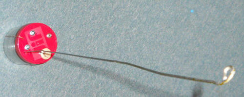
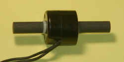
This simple receiver is built into a plastic peanut butter jar and uses a straightened coat hanger for the antenna yielding a length near 32 inches. A block of wood attached to the lid by two screws stiffens the lid and supports the antenna and ground wire. Two additional screws secure the antenna and one screw holds the ground wire. The enamel was sanded off a a section of the coat hanger wire to allow the attachment of a short length of hookup wire:
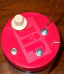
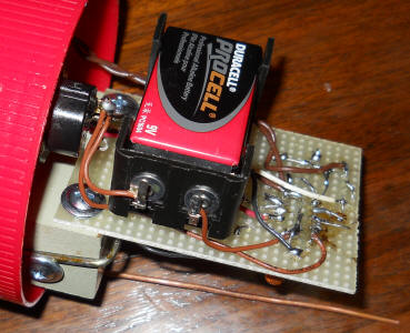
The ground wire is a 9" length of 14 AWG solid copper wire like that used in house wiring and it is simply bent down along the jar so that it makes good contact with the hand while the unit is in use. (The body serves as the ground for the receiver - don't forget to grab the wire.) A volume control and output audio jack are also mounted in the lid. The block of wood also serves to support the circuit board and battery holder.
![]()
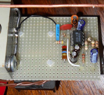
The first amplifier is biased to half the battery voltage by the two 1 meghom resistors through the 22 meghom resistor. Pin 1 should sit near 4.5 volts when operating. The gain of the first stage is 23 and may be increased to 48 by changing the 22k resistor to 47k. The volume control/switch isn't critical but use a larger capacitor to ground on the bottom of the pot for lower values. Use 10 uF with a 10k pot.
When you turn the unit on in the house you should be "blasted" by hum after the circuit comes alive. It will be pretty useless indoors. Go outside as far away from buildings and power lines as possible. Touch the ground wire when operating the unit. A good pair of modern headphones will help, especially noise-cancelling types. The circuit will also drive an older crystal earphone. When you get away from all the hum, you should be able to hear faint crackles that sound a little like frying bacon and little chirps from more distant lightning. Storms within a couple of hundred miles will be quite loud. You can probably hear your own footsteps, too. For some stereo headphones you may need to connect the tip and ring of a stereo connector together to get sound in both earpieces. You can also use the tip for the output and the ring for the ground, thereby connecting the earpieces in series. See the version below with the hum filter.
![]()
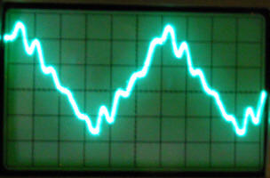
Hearing these signals requires little more than an audio amplifier and an antenna since they are in the audio frequency range. But the ever-present power line hum makes listening to these signals difficult in suburban areas. Free software is available to digitally clean up the signal, making natural radio listening a practical home-based activity. A tremendous freeware offering from Wolfgang Buescher (DL4YHF) called "Spectrum Lab" works in conjunction with the sound card to display the frequency spectrum and a filter is included to remove annoying interference. Karen, a reader in the U.K., developed the "Humnuller," a simple application that also does the trick. It has the nice feature that you can click a button after an interesting sound and capture a previous window of time (user selected). Here is what it can do: My antenna without the filter With the filter .
In some circumstances the 60 Hz fundamental can be so big that it causes non-linear behavior in the amplifier, imparting a "hum" onto all the sounds or it drives the amplifier to the rails, totally killing the gain to interesting signals. A 60 Hz notch filter is usually a good idea for these circuits. A simple filter that works well is the twin-T notch. For hand-held units with relatively short antennas it can prove tricky to design a twin-T notch filter to connect directly to the antenna because the filter components can load the antenna excessively. I've done it with carefully selected high-value resistors with some success. However, it turns out that the entire filter can be bootstrapped to greatly reduce its loading effect without hurting (actually helping) its filtering. The bottom connection of the filter is connected to a buffered version of the input signal (with no gain) instead of ground. Such a signal is often available at the summing node of the first op-amp but it's safer from a stability standpoint to make an independent signal with a voltage divider.
To illustrate the idea I modified the Peanut Butter Whistler Radio above to include a notch filter. Notice that the voltage divider driving the bottom of the filter has the same values as the gain resistors, 47k and 1k:
The values in the filter are critical and the resistors may be made by combining standard 1% values as shown. (The .01 uF leading to the antenna is not critical; It's not even necessary in most cases.) The capacitors should be hand-selected using a capacitance meter. Combining two .01 uF in series to form the .005 uF allows high and low values to be combined to hit the desired value closely. Shoot for better than 1% accuracy. The 3.3k in the bottom resistor group could be a 5k pot to allow fine-tuning. Use good-quality audio capacitors, typically polyester film types. You can use other values near these but 1/(6.282 * R * C) should be very near your line frequency. (R and C are the top values; the two vertical components are 1/2 R and 2 C.) You can adjust the resistor to ground a little to tweak the filter but the notch becomes less deep as the value deviates from optimum. You don't really need a tremendously deep notch in most instances.
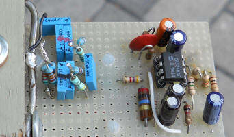
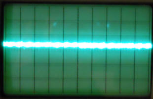
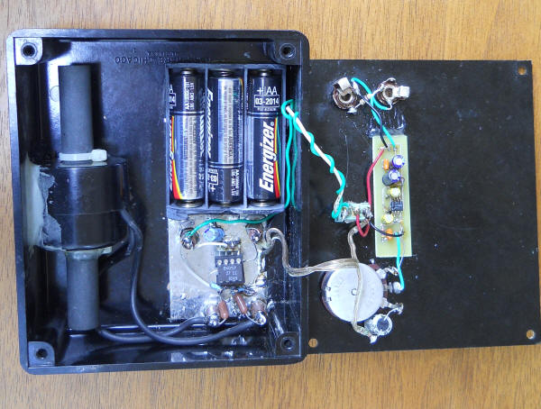
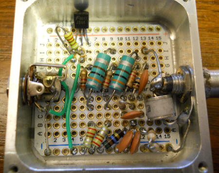
Here are before-and-after photos from a 'scope. The new filter is to the left in second photo and consists of metal film resistors and blue film capacitors. Note that I marked the matched caps with paint to keep them together. Each pair consists of a .01 uF that is a little high and a little low, giving .005 uF that is dead-on according to my capacitance meter. It helps to start with a big pile of caps! Also notice the larger 470 uF cap connected to the 1k near pin 2. It's quite large because the phase shift needs to be low at low frequency to avoid a resonance. If you use LTSpice try this circuit to see the effectiveness of bootstrapping the notch filter (use the AC analysis). Lower the 470 uF in the simulation to 1 uF to see why it's so high a value.
The harmonics of the hum will still annoy you! But that's where software filtering comes in.
![]()
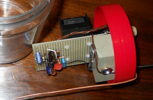
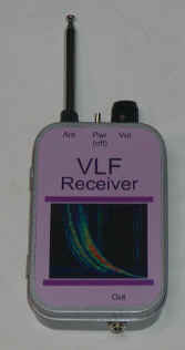
Here is a tiny receiver built into an Altoids tin suitable for use with a laptop computer or portable tape recorder, earphones or modern headphones. The prototype antenna is only 1 foot long when fully extended and the receiver fits into a shirt pocket.
 |
 |
(I bought a rail of CA3140s, too. Modern op-amps tend to be quite specialized.)
In this version, the FET preamplifier inverts the signal and the op-amp is non-inverting. It's important to have signal inversion between the antenna and output connector to prevent squealing feedback.
Any n-channel JFET with an Idss of at least a few mA should work, but add a 1k ohm in series with the gate. If oscillation occurs, try adding a capacitor to ground across the 100 megohm resistor, perhaps 22 pF. | |
The 1k resistor in the source is only a starting value and it should be selected to achieve about 5 volts on the drain (400 uA). With some JFETs with high Idss, this value may be considerably higher than 1k depending on the FET. | |
The 100 megohm bias resistor may be several 22 megohm resistors in series and the value is not critical. A higher value (or longer antenna) will give better low frequency response but that only invites line frequency troubles. Stand reasonably still when listening or changing electrostatic fields will overload the amplifier, especially if you are wearing rubber sole shoes. | |
The 50k pot may be a higher value if desired but don't drop much below 25k or gain may suffer. If the op-amp is fast enough, more gain may be had by increasing the 100k feedback resistor. My brief experiments indicate that the gain is plenty high as-is. | |
The 1uF capacitor in the source and negative op-amp input are on the low side to reduce line-related hum and they may be reduced to give the circuit even more of a high-pass characteristic to reduce overload from line frequency. The 22uF in the output may also be reduced for the same purpose. In extreme cases, try 0.47 uF caps for these three caps. (The output cap is presently large to accommodate low impedance loads.) | |
The op-amp may be just about any type that will work with a 9 volt power supply including most CMOS types, "single-supply types, and low power types. | |
There are two capacitors indicated across the power. Place the 1 uF near the op-amp and the 47 uF near the FET. If your circuit has stability problems, break the line between the two capacitors and add a small resistor, perhaps 100 ohms. (Keep the op-amp on the battery side of the resistor.) |
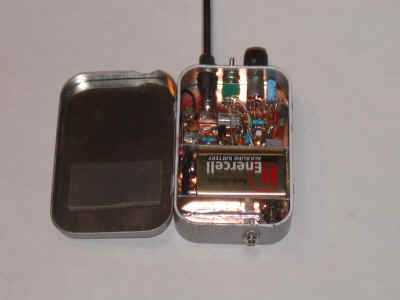
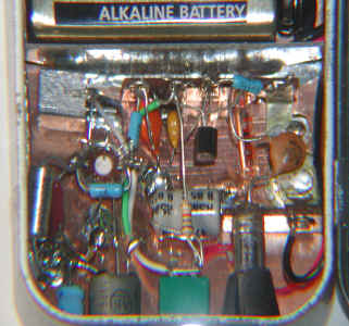
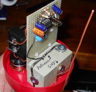
I painted my tin with gray hammertone paint and affixed a label to the lid. The circuit is built on a piece of polished copper clad circuit board sprayed with a light coat of clear Krylon to keep it shiny. All the ground connections are made directly to the copper and a couple of terminal strips hold most of the components. A battery compartment is formed with two pieces of copper clad board soldered in place as walls and a piece of foam rubber on the lid secures the battery. Just about any assembly technique should work fine so don't feel compelled to copy this approach.
![]()
if you just can't wait to try something, this little receiver is for you! The whole thing is built into an earphone plug. Laptop computers, microcassette recorders and the newer digital recorders have plenty of gain to use with this device.
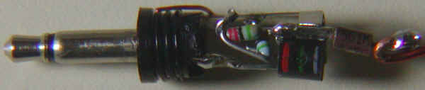
This circuit receives power from the microphone input on the laptop or audio recorder. The drain of the FET connects to the center pin or to both the tip and ring pins for a stereo plug and the source connects to the ground pin. I recommend the stereo plug for the greatest compatibility (unlike the picture). Two, 22 megohm resistors are connected in series from the gate of the FET to the ground pin and a 560pF capacitor connects from the gate to a flexible wire antenna about 14 inches long (not critical at all). The capacitor value isn't critical and a smaller value will work fine. I selected it for its mechanical strength! For the antenna, use wire that is stiff enough to hold its shape but bends easily enough to protect your recorder's jack. The JFET I used is like the 2N4117 with an IDSS of only about 125uA so power consumption is quite low. I'd recommend an FET intended for microphone preamps like the J201. This thing really works! I just walked out to the end of my sidewalk and made a recording. A car passed near the end and the electric fields produced by the tires make quite a roar. There was no lightning for hundreds of miles but the spherics are easily heard. The hum was removed by Spectrum Lab and the file was down-sampled using dBpowerAMP to make the file small. (I could have used Spectrum Lab for that, too.)
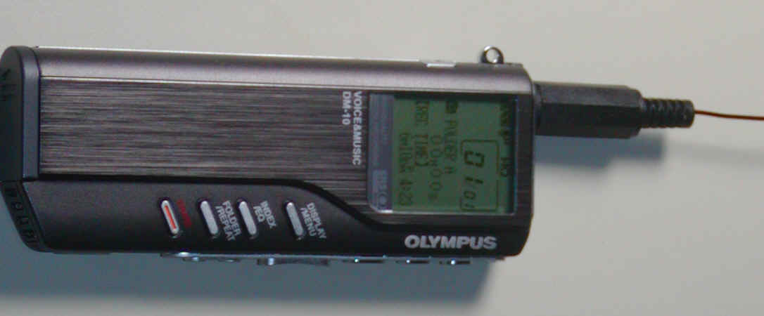
As is often the case with quickie projects like this, a problem arose; the antenna picks up the LCD mux frequency. I tried shielding the connector and lower portion of the antenna and it helped greatly but it didn't look very nice. The solution is quite simple; just use an earphone extension cord. The cord lets you easily hold the antenna over your head while keeping the recorder comfortably low, anyway. Yes, that's the ticket; its a feature... Or, find a metal box that the recorder fits inside and connect the box to the recorder's ground, perhaps at the earphone jack.
Note: The audio input on these recorders can be "tricky". Mine looks at the impedance of what is plugged into the earphone jack to decide whether it is a microphone or earphone and whether it has stereo capability. It seems to do a test at the instant of initial connection and remembers the results until the plug is removed.
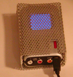
I had the same problem with a much better recorder, the M-Audio Microtrack 24/96 It's a fantastic recorder but it emits a huge amount of hum and buzz and a receiver can't be anywhere near it. A lot of it sounds just like 60 Hz line noise, too, making it more confusing. I came up with a solution that completely eliminates the interference:
Having battery problems with your Microtrack?
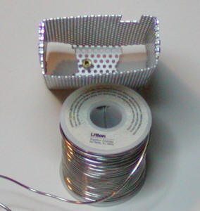
I formed a shield from perforated aluminum, using aluminum eyelets to hold it together. The "trick" is to add a short 1/4" dia. brass standoff on the inside that lines up with one of the 1/4" jacks so that the shield is grounded when the standoff plugs in (second photo). Keep the standoff short, maybe 3/8", so that it doesn't reach the input terminals in the socket.
The simplest antenna for natural radio is an electric pickup consisting of a wire or metal rod. A long wire antenna typically used for shortwave listening can also work well but a simple vertical whip is better. The reason is that a long wire antenna is likely to pass near trees and bushes. When wind tosses them about, the static charge on the foliage can induce audio noise into the antenna, essentially turning your antenna into a huge electret microphone. Even a bee buzzing around the antenna can induce audio! I prefer a vertical antenna to get the antenna as far away from the house and trees as possible. I have a somewhat tentative theory that suggests a significant portion of the interesting signals are electrostatic in nature, not carrying the penetrating power of an audio-frequency radio wave. That means you want the antenna away from other conductors like trees and bushes that can shield the antenna from the desired signal.
I've come to the conclusion that the most practical fixed installation consists of a high antenna, preferably away from the house and power lines hooked directly to a long lead-in coax and good earth ground. At first, it might seem like all that cable capacitance would attenuate the signal too much but sufficiently low-noise amplifiers are easily constructed. Having all the electronics in the house is eminently more practical and convenient. The extra capacitance from the antenna cable becomes a handy circuit element for some simpler receivers. This first receiver uses an ordinary twin-T notch filter that doesn't require the bootstrapping technique described above and an ordinary darlington transistor as the gain element. As a point of reference, when connected to my rooftop antena with about 750 pF of additional cable capacitance, the CA3240 circuit above exhibits a noise floor about 15 dB below the lowest atmospheric noise I've seen on a quiet day at 2 kHz. The caveat is that I live in an electrically noisy place. The old yet still available LF356 is a little lower noise than the CA3240 below 2 kHz and modern FET amps are available that are even lower noise. But it's good to have some resistance in series with the op-amp to reduce the effects of radio stations so that resistor will set the noise floor with the better op-amps. It isn't likely that any of these op-amps will be adding significant noise with a reasonably long antenna and modest cable length.
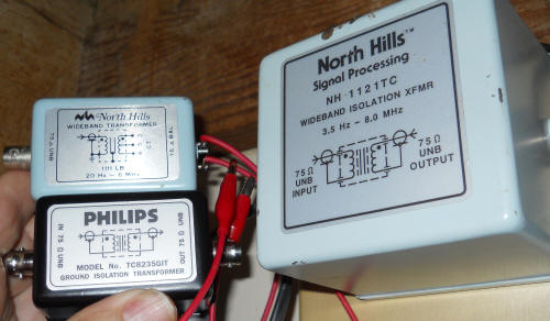
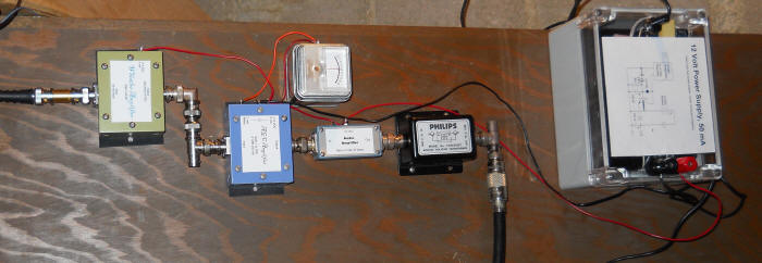
Fixed installations can benefit greatly from an isolation transformer between the receiver and the computer. "Video isolation" transformers are readily available, my favorites being a North Hills 1111LB and the much larger and wider band 1121TC. I also have a Philips TC8235GIT that works well and there are plenty of other types and models. The idea is to break the ground connection between the antenna circuit and the computer, and also the house wiring when practical. Here are two traditional video isolation transformers held next to the huge 1121TC that is my "permanent" isolator. The small North Hills has a couple of clip leads on the secondary terminals (instead of a BNC) and that's handy for experimentation with grounds and antennas. These transformers have an extremely wide specified bandwidth, 3.5 Hz to 8 MHz in the case of the 1121TC, but that's when driven by and terminated with 75 ohms. So it is best to use an amplifier with a fairly low output resistance to drive the transformer and use a 75 ohm termination at the sound card. The values aren't critical for audio work.
"Ordinary" audio transformers will also work well, especially older microphone transformers or audio interstage transformers.
This receiver is powered by the computer's sound card. You may need to short the "tip" and "ring" of the stereo plug for most soundcards. The tip is usually the audio input and the ring provides the power. Also mute the microphone in the sound card control window since the audio will most likely be processed by a program. Otherwise you will hear the program's output and the direct audio at the same time. You may find a microphone boost check box that will give you more sensitivity if needed.
The antenna for this receiver is about 2 meters long, mounted high over the roof of a home. The lead-in cable is about 30' long and has about 750 pF capacitance. That capacitance attenuates the signal quite a bit, perhaps about 30 dB, but the atmospheric noise is still well above the noise of the amplifier.
The MPSW45A has excellent specified noise performance of only 25 nV/root-Hz and 150 fA/root-Hz. The noise voltage is as low as the 47k series resistor and way below the 1 megohm often seen in these circuits! Noise current is often the big problem with bipolar devices. The prototype measured only 47 fA! As a point of reference, the excellent bipolar op-amp, the OP37, is specified to have a noise current of 400 fA. Low noise current is more important when the antenna and coax have little capacitance. In this instance, the noise voltage dominates down to below 300 Hz and consists primarily of the darlington noise and resistor noise. The noise voltage was measured near 100 nV at 1 kHz and that includes the noise current effects, too. On the quietest day I've seen so far, the atmospheric noise was over 1 uV/root-Hz even with all that cable capacitance, well above the noise of this amplifier. This darlington would be serviceable in setups with capacitance as low as 75 pF. Most designs include that much total capacitance at the input, often adding 47 pF or so to help reduce radio station interference. And the darlington is practically bullet-proof - I've never lost one to a surge.
The Lumex device is similar to a neon bulb but designed to handle large currents. Any sort of gas discharge device will work here, including a simple NE-2 lamp. You could alternately include a "coaxial surge protector" in the box (search Amazon with that phrase). The 10 megohms across the antenna bleeds off any charge and the value can be low since there's so much cable capacitance.
The filter is a bit fussy. Measure the caps and resistors with a multimeter. The 270 pF caps and 10 megohm resistors in the filter aren't perfect values for 60 Hz, being a little on the high side but you can select caps or resistors to be a little on the low side by about 2%. I simply used a 511 pF for the cap to ground to shift the frequency a little. That hurts the notch depth a little but the purpose is simply to knock down the huge signal so that a sound card can handle it. It isn't necessary to obliterate it. The filter may be tested with an audio generator and oscilloscope without the darlington being powered; inject the signal at the antenna connection and use a scope probe to look at the signal on the top of the 47k resistor.
For 50 Hz environments, increase the values of the two top capacitors to about 330 pF and experiment with a value near 620 pF for the one to ground.
The 1N4750 is there to limit any negative-going pulses caused by the gas discharge tube firing. The darlington base handles the positive pulses. Try the LTSpice model to experiment without a soldering iron. This model reflects the values in the prototype - feel free to change them.
Note: you may get better results with a "video isolation transformer" between an amplifier like this and your computer as described above. The problem is that this circuit gets its power from the computer, so connect the transformer as a common-mode choke, with the primary connecting between the amp output and sound card input and the secondary connecting between the two grounds. Don't be surprised if it just makes things worse; the phasing might be wrong. Try reversing one of the windings, in case the phasing is incorrect. It's important to have a good ground for the antenna, preferably a buried metal water pipe or something similar. It's okay to run a long wire over to the ground for reception purposes, it's just audio, but a straight, heavy wire to ground also helps protect from lightning damage. A commercial surge arrestor like those used for satellite TV systems is a good idea. Search for "coaxial surge protector" on Amazon for an example; they're as little as $4 and contain a beefy gas discharge device. Try to run a heavy wire straight to a good ground from the protector's body; some even have a screw for the wire.
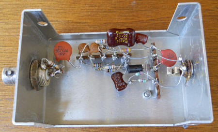
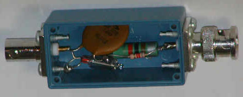
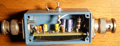
I added this additional surge protector to my antenna:
It has a heavy-duty gas discharge device and a 62 megohm resistor across the antenna connector, a high-voltage 0.1 uF capacitor in series to the output connector, and an ordinary neon lamp on the receiver side of the capacitor. The cap is big in case I want to experiment with circuits up at the antenna. The blue box has a ground terminal on the back that has a heavy wire running over to a cold water pipe.
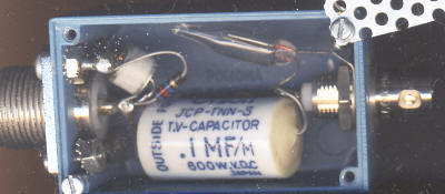
When I was using the antenna only for VLF reception, I had a different surge protector box:
This box also helped to keep AM radio stations out of the amplifier. It should have a bleed resistor, too, perhaps a couple of 22 meghoms in series from antenna to ground. It's best to disconnect the antenna when not in use.
![]()
This receiver is designed to work with a speaker or headphones or with a computer or recorder. When the electret microphone output is used, the voltage from the computer or recorder that would normally power the microphone instead turns on the preamplifier section of the receiver, bypassing the power switch. (Disconnect the plug when not in use.) When the power switch is turned on, the LM386 also receives power to drive a speaker or headphones. The notch filter is bootstrapped so the circuit will work well with a short antenna with little capacitance or a rooftop antenna fed by a fairly long cable with lots of capacitance.
The CA3140 draws about 2 mA at 9 volts and that will run the battery down after a week of steady use. But it would also be possible to substitute a micro-power FET type op-amp to reduce power consumption when not using the LM386 to the point that the battery shelf-life would dominate. The original FET version was abandoned because many new computers supply a very low voltage to the microphone, as low as 2 volts. That doesn't leave much headroom for more than running the active device. This technique of using the microphone voltage to activate the battery-powered circuit allows sufficient voltage to bootstrap the bottom of the notch filter while providing plenty of gain.
Notice that the notch filter is bootstrapped from pin 2 of the CA3140, saving two resistors.
Also notice that this design "violates" the inversion rule where the output should be an inverted version of the input. The metal case helps a lot but it will squeal if a poorly-shielded audio cable is held near the antenna (such as a crystal earphone cable). Good headphones usually have well-shielded cables and seem to work fine. When using this device as a portable unit the hand touching the case provides an important "ground".
The gain of this circuit is very high and may be reduced by reducing the 100k feedback resistor connected to pin 6 of the CA3140 or by adding a resistor in series with pin 1 on the LM386 (or doing both). When using an outdoor antenna, add a surge suppressor box with a high-value bleed resistor to ground. Add a DC power option for long-term use with a computer. A power jack could be wired to apply power to pin 7 of the CA3140 while disconnecting the 2N4403 collector (using a power jack with a built-in changeover switch).
I reused an old audio amplifier (right) and simply insulated it with heat shrink tubing:
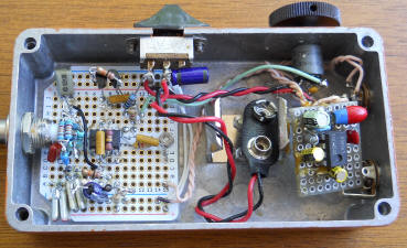
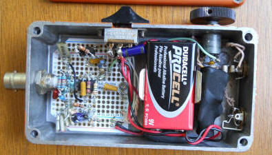
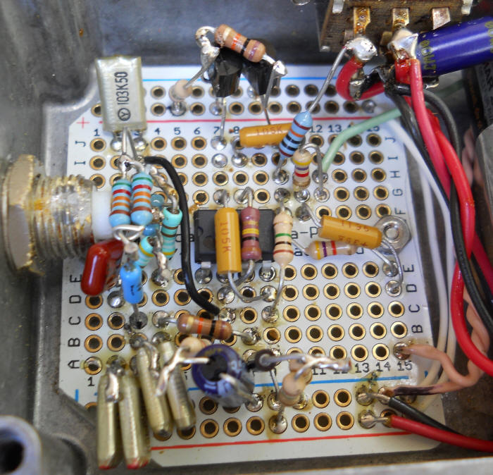
I've discovered that one's hobby time can go a lot further if one isn't too concerned with internal neatness! As long as the construction is rugged and reliable it will do! The Adafruit prototyping boards allow for amazingly quick prototyping and great density if one is willing to move into the third dimension. Notice how many of the parts are wired up in the air. The two-transistor power switch only uses one dedicated board trace plus power and ground; all the rest is wired in the air or goes to traces already used. The notch filter is similarly air-wired. The board gives the whole structure plenty of mechanical integrity. There's a thin sheet of epoxy-fiberglass board under the circuit board to prevent component leads from touching the case. That allows construction from the top side - every component on that board was soldered in after the board was mounted in the case, thanks to the high-quality plated holes. Despite all the parts, there's still ten or eleven traces available. : )
The original circuit is shown below for "historical purposes." Use a 2N4338, J201 or similar low pinch-off JFET. The notch filter isn't bootstrapped so the very high-value resistors and small capacitors are an attempt to load on the antenna as lightly as possible. The circuit does invert the signal which is better for stability. Another distinct advantage is that the power is completely supplied by the computer when that jack is used. The high-value resistors were formed by selecting 22 megohms to connect in series to get an accurate value.
![]()
While staring at an otherwise useless 900 MHz baby monitor, it occurred to me that the circuit to operate its microphone is perfect for operating a transistor for a VLF receiver, something along the lines of the Computer Powered VLF receiver or the Super Tiny VLF Receiver. I chose the Super Tiny version and added a 330k resistor in series with the gate to cut down on intermodulation products from radio stations. Here's the contraption:
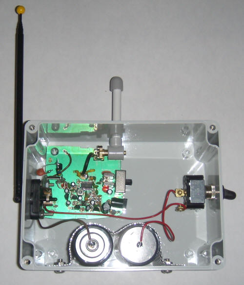
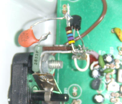
The baby monitor is removed from its case and mounted in this larger one along with two D-cells, a power switch, and the Super Tiny VLF receiver circuit. The original baby monitor antenna is the short gray one and the VLF antenna is the longer black telescoping type. The close-up of the VLF receiver below shows a 363k resistor and 750 pF capacitor from the antenna (Fahnstock clip) to the gate of the J201 JFET (or any type suitable for low voltage application). A 47 megohm resistor connects the gate to the source and ground (and also the microphone cable's shield) and the drain simply connects to the microphone cable center conductor.
The range of the baby monitor is great (using an old scanner), and the fidelity is surprisingly good. I'll be keeping my eye out for more of these in the garage sales! The purpose of this gadget is to listen to unusual local VLF signals like passing cars, buzzing bees, etc. I rushed it together to try to catch a hoard of bicycle riders that occasionally pass my house in the middle of night. (They're an odd bunch that go for all-night rides on the occasional full moon!) Unfortunately, their route didn't pass the house this time. But I did catch a couple of other sounds during the day. A couple of notable examples below were recorded with Karen's Humnuller program.
Bug buzzing the flowers by the roadside.
The VLF antenna was near the ground and sloping over the flowers, adjusted for minimal spherics.
A couple of loud tweaks can be heard just as the car passes, not to mention an unusual whine. That car must be a hybrid! Most of them just roar. The antenna was horizontal and near the ground under my truck for this recording. That turned out to be a questionable location, by the way! Not only did several neighbors become alarmed by it, but a couple of police officers also spotted the thing. I must admit, it does have a bomb-like appearance! It spent the rest of the night under an overturned flower pot with the VLF antenna sticking out the little drain hole in the bottom.
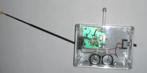
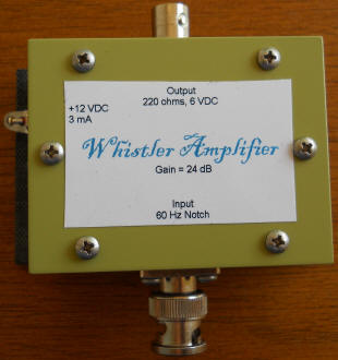
That's the completed unit with the cover installed. It should be quite weather resistant and the batteries will last for several days of continuous operation. This battery-powered receiver can be placed quite a distance from the house and overhead wires yielding some of the cleanest reception I've heard. I might add provisions for a ground wire to clip to a metal rod, car chassis, etc. The impedance of the amplifier is so high that a pretty terrible ground connection is adequate. I've had great luck with an old steel rotisserie skewer connected with a length of hookup wire. Just stick it in the ground - even dry soil seems to do the trick.
Any audio gadget that uses one of those silver can microphones can be modified in this manner. Whatever the device is, it already has plenty of audio gain for the microphone and it supplies the required bias current.
![]()
Find a way to have a three meter (or longer) vertical antenna mounted on at least a three meter mast above the roof, preferably away from any trees. The antenna and mast should be stiff and not have any moving or flapping parts. My antenna is the top portion of a military antenna sticking out of an unused flu in my chimney. The tip of the antenna is about 16 feet above the roof. Run a cable from the antenna to the radio room with as short a run as is practical but up to 10 meters or even more is fine. It's a good idea to add a series gas-discharge surge suppressor in line with the coax with a heavy ground wire running as straight as possible down to a buried water pipe or other suitable ground for diverting surges due to lightning. Add another surge suppressor to the end of the cable and connect the case to the local earth ground, often a cold water pipe or wire running in a window from a deep grounding rod. These details are discussed above under the Computer Powered Receiver. I'm using this suppressor at the receiver:
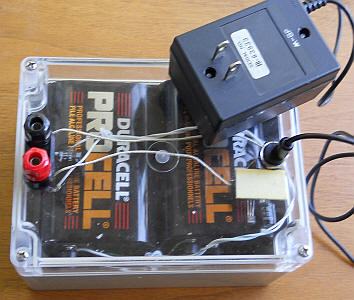
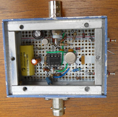
Building all the circuitry to run on a single +12 to +15 volt supply simplifies the power supply and makes battery backup easy. Battery backup is highly recommended since listening is often most interesting after a power outage! Find a small but linear power adapter that is rated at 18 or more volts and build a regulator to supply the +15volts. Alternately, you might be lucky enough to find one that includes a linear regulator. Battery backup can be quite simple; just pass the regulated voltage through a Schottky rectifier to the load and connect a 12 volt lantern battery through another such rectifier to the load. When the line power is good, the load gets 15 volts minus a few hundred millivolts and the battery rectifier is reverse-biased. (I actually used an adjustable regulator set to 13 volts.) When the power fails, the battery supplies 12 volts minus a diode drop and the other rectifier prevents current from flowing into the regulator. Current draw will be low so the batteries should last through decades of power outages.
The preamplifier is similar to the earlier design using the CA3240 but with additional RF filtering. I was going to plot the actual response but it is identical to the Spice plot. I pushed the frequency response out to be 3 dB down at 185 kHz to allow reception of LowFER transmissions but the gain is well down by the AM broadcast band to keep radio stations out.
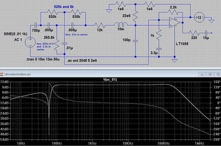
I built the notch filter on a little board and "potted" it in orange electrical tape. It becomes a three-legged part and takes up little board space. The op-amp is the venerable LF356. (The LTSpice circuit uses a similar part that was in the component library.) The gain is fairly low, just high enough to get the signal out of the noise as this circuit will be driving an AGC amplifier.
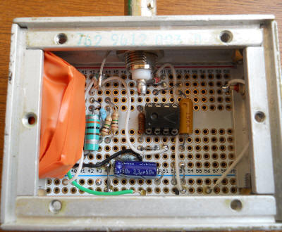
Note that all op-amps are in sockets. Lightning can be destructive.
NOTE: You may wish to skip the AGC amplifier that follows and set the gain of the above amplifier as high as needed. You should be able to get sufficient gain before running into bandwidth limitations with the LF356. It would drive the buffer (Step five below) directly. Start with a 47k feedback resistor for a gain of 48 and reduce it if you get clipping. You can also reduce the input attenuation of the buffer below for up to 20 dB more gain without suffering bandwidth issues.
The AGC amplifier can be undesirable if you wish to also monitor other signals like SIDs or beacon transmitters.
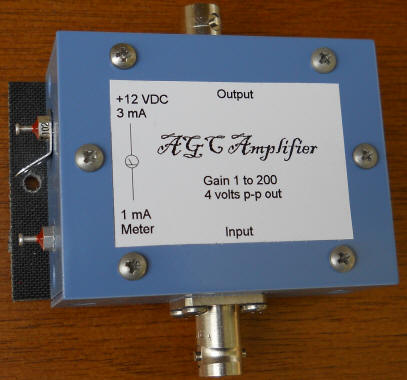
The AGC amplifier below is shown using a Raytheon CK2143 CdS-based optoisolator but others will work as will a homemade one made by gluing a CdS cell to the end of an LED (see the AGC Dynamic Microphone). A 1 mA current meter connects from +12 VDC to the cathode of the optoisolator's LED to indicate the ACG activity. (Ask me about where to find the CK2143.)
The AGC amplifier can be tricky to set up properly:
|
First, determine how much signal should be coming out of the amplifier during quiet periods. I chose about 4 volts p-p because I'm in a residential area where there's a constant signal from the AC line voltage. In a very quiet location it might be more appropriate to set the output lower, say 1 volt p-p, by reducing the 3.3k AGC Set resistor, perhaps to 1k or so. Otherwise the gain might be unreasonably high and the signal will need to be attenuated later anyway. The AGC set resistor could be an external control. | |
|
Second, measure the gain for various signal levels and AGC
current meter readings. It is desirable to run the AGC amplifier at about a gain
of 50 to 100 during quiet periods so adjust the preamplifier gain ahead of this AGC amplifier to get the desired meter reading. Realizing much more gain in the
AGC amp will start to limit the bandwidth and much less will start to use up AGC
headroom. The AGC can reduce the gain to about 0 dB (40 dB of range when the nominal gain is
100). | |
|
Third: the attack time is pretty quick but the decay time is very, very slow due to the 4 uF. This very slow response prevents the gain from changing much when there's lightning nearby and gives a more pleasurable listening experience. But it takes patience to test the circuit. It takes minutes for the gain to increase. |
I think this amplifier is fun to play with but you probably don't need it and it is actually undesirable for certain purposes. See the red text at the beginning of step four. I bridged the photocell in mine with a maximum gain pot so that I could set the maximum gain to a low enough value to stop the AGC action until a storm is nearby. That keeps the gain at a fixed level which is better for monitoring SIDs or beacon transmitters.
A simple LM386 amplifier with an input attenuator and a 68 ohm output resistor will exhibit about a gain of two into a 75 ohm load, such as a video isolation transformer. In my setup the final gain was too high for driving the line input of a sound card so I increased the 10k to about 22k. After loading the far end of the audio coaxial cable with 75 ohms, the levels were just right. If you choose to skip the AGC amplifier above, you can pick up a little gain right here by lowering the 10k or even shorting it for a full 20 dB gain. The bandwidth is around 300 kHz, plenty for monitoring SIDS or LowFER beacon transmitters.
The total current for all the electronics is 15 mA. The lantern batteries would last for about 30 days of continuous use.
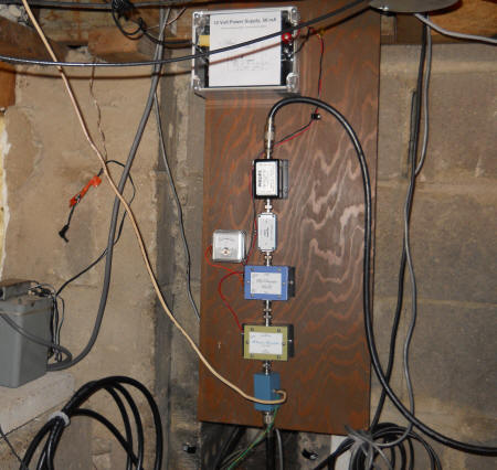
When this is all working to my satisfaction, I'll hang the board on a wall where the antenna enters my basement. The modules are easy to work on but I find it even better to take the whole thing over to the bench so I'll make the hangers easy to release. There's a Tee on the input to the AGC amplifier in the event I want to use the preamplifier's output for higher frequency reception. I'll move that to the antenna since the Whistler Amplifier doesn't load the antenna at all. A future RF amplifier for LF signals would also need a very high input impedance. The current meter is at 1/2 scale with lightning in the area and that corresponds to a gain around 50. I therefore have 34 dB of AGC headroom.
The cable on the left is the antenna connection and the cable to the right is the audio that runs off to a computer. That second cable is terminated with 75 ohms at the far end and the signal is quite large, plenty big to drive the line input of a sound card. I use Spectrum Lab's oscilloscope function to see how I'm doing regarding signal size. Wolfgang's site has excellent information on how to get the sound card working properly with Spectrum Lab. I usually use Karen's Humnuller for regular listening.
Future modules might include a noise blanker. Strong pulses cause the computerized hum filters to make a "bzzzt" or "bong" sound (Spectrum Lab and Karen's Humnuller, respectively) and a noise blanker that chops off the tops of such pulses would greatly reduce that effect without hurting the more interesting sounds.
A microprocessor humnuller like Karen's PIC Humnuller might be added in the future, too.
Currently, I use the Unfair Radio Transmitter to allow listening all over the house. It might be nice to have a 5 volt version that runs on the Laptop's USB power so that everything keeps working during a power outage. Now, I'm confined to proximity to the laptop's speakers when the power is off.
Done:
Seeing just how big my hum signal is (even after nulling the 60 Hz component) makes me wish I had proceeded in a slightly different manner. I'd use one CA3140 as a simple voltage-follower to bootstrap the bottom of the hum notch filter; that's all it would do. Then I'd connect the AGC amplifier's input in parallel with that follower, simply connecting the positive inputs of the op-amps together. The AGC amp would run at higher gain, giving a little more AGC headroom, not that it's needed.
Skipping the AGC amplifier altogether is an option for those who don't listen during storms (generally a good policy). But I can't really hear whistlers here in the heart of Texas and a nearby storm makes for some amazing listening (especially when the surge suppressors start conducting :). I'm impressed that nothing ever fails, a testament to the surge suppressors. I've capped the AGC amplifier gain by adding a shunt resistor across the photocell so that AGC action only occurs during a storm. That keeps the gain fixed most of the time for SIDS and beacon monitoring.
![]()
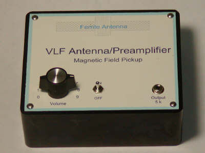
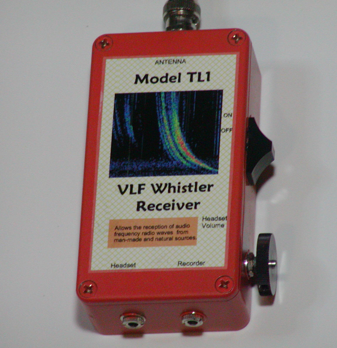
There are two approaches for receiving the signals, a loop or coil antenna that picks up magnetic fields or a whip or wire antenna that picks up the electric field. The prototype magnetic pickup coil shown below is made with a common 120 volt valve coil. Its 1/2" dia. hole perfectly accommodates the larger Amidon ferrite core (R33-050-400). (These removable coils slip over an enclosed solenoid and are commonly used in industrial equipment valves. Make sure to take them out of the metal housing and remove any metal parts.)
The core is simply secured with a cable tie on each side of the coil. The resulting inductance is about 900 mH. The loopstick is hot-melt glued into the case as is the circuit board and battery holder. The front panel was designed with a CAD program, printed on glossy report cover stock and sprayed with a clear coating. Spray adhesive holds the label to the Bakelite cover.
(I added another jack with a 4.7k in series for use with a sound card.)
My previous version used much larger resistors in the input circuit (with the same ratios) and that reduces the gain at low frequency. The low frequency end of the spectrum is pretty noisy so that little trick can flatten the spectrum for use with a spectrum analysis program.
A twin-T notch filter could be added between the first op-amp and the LM386 for urban listening.
![]()
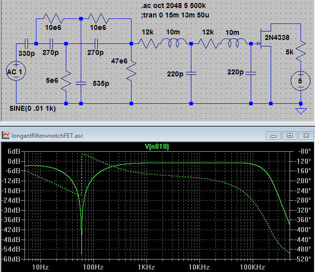
Here's a simple circuit for connecting to a vertical whip or long wire antenna for receiving audio frequency signals. The antenna plus cable should exhibit about 330 pF of capacitance to ground so add shunt capacitance as needed. This circuit is intended for setups where the antenna is connected via a fairly long piece of coaxial cable.
The notch frequency may be adjusted slightly by adjusting the 535 pF capacitor so that should consist of a fixed value, perhaps 470 pF and a variable trimmer, say 0 to 100 pF. Adjust the trimmer for the deepest null of the line frequency. The 5 megohm could also be adjusted in a similar manner with the theoretical value being near 4.9 megohm for 60 Hz.
The FET may be any of a number of types suitable for microphone amplifiers; I also like the J201. the 5k and 5 volt power source represent the circuitry on a typical soundcard. Just connect the drain of the FET to the tip and ring. The main problem with this approach is that there's no isolation between the receive ground and the usually-noisy computer ground. Despite this noise source, a high outdoor antenna seems sufficient.
OK, this has moved on from being virtual:
I made this for a friend and it's every bit as flat as the Spice plot. This needs to replace most of my other front-ends!
![]()
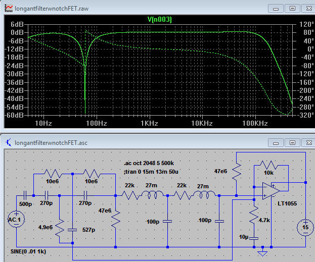
Here's an op-amp version. The op amp can be any number of FET input types, especially JFET types which have fairly rugged input stages. (I like the LF356 here.) Note the unusual feedback to the bottom of the twin-T filter. That voltage bootstraps the bottom of the T, reducing the loading effect of the 4.9 megohm resistor. The 4.9 meghom resistor could be a 4.7 meghom in series with a 150k and a 100k pot and the 527 pF capacitor could be a 470 pF in parallel with a 47 pF and a 20 pF trimmer. Those variables would allow the notch to be fine-tuned, if desired. The 27 mH chokes are molded types - nothing special. This circuit is best for longer cable setups. Note the 500 pF at the input; that represents a fairly long coaxial cable to the antenna. Such a long cable significantly attenuates the signal but the RLC filter is much lower noise (about 25 nV/root-Hz) than the typical 1 megohm resistor (about 125 nV/root-Hz) often used at the front-end of such receivers. The result is that the atmospheric noise is well above the electronics noise for reasonably good op-amps by about the same amount as traditional receivers with direct connection to the antenna (with that 1 megohm in series). Note the nice, flat response out to 100 kHz followed by a steep drop thanks to the RLC filter. RC filters are adequate and eliminate the need for the inductors (see the next schematic).
![]()
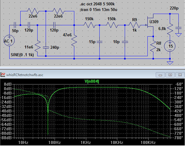
Here's a transistor version for direct connection to a short antenna as with a portable receiver. (Add about 39 pF to ground across a 1 meter antenna to get close to 50 pF.) Notice that the source of the JFET drives the bottom of the twin-T notch filter, increasing its Q and reducing the loading caused by the filter. This circuit also uses unusually high reactance in the notch filter to help reduce the loading. The 11 megohm and 240 pF may be a combination of parts as described above for fine-tuning the notch or the notch can be fine-tuned one time with fixed components. This circuit is quite low noise and will work well with just about any antenna setup. The roll-off of the AM band isn't as steep as with the RLC filters above but the attenuation should be sufficient. The 15 and 10 pF caps may be increased for a lower frequency corner. The output may be taken at the 6.8k and a buffer is recommended here. The voltage is about 9 volts on the drain and that can be used to drive a simple emitter-follower.
![]()
Alysson sent a couple of compelling emails regarding whistlers that I have combined into one below. Although I have no scientific basis for my thoughts, her explanation seems on target. It is easy to imagine that a batch of high-velocity ions from the sun arriving near a pole will spiral in the earth's magnetic field and will radiate energy in the process. As they slow down it makes perfect sense that the frequency will drop. Diffuse whistlers might be due to a spread in arrival times for larger clouds of ions. I personally don't see the connection to lightning (that's not saying much) since the ions will travel in spirals simply due to their kinetic energy and the magnetic field. Also, since all the "whistlers" I've picked up in Texas have been motors, I wonder if the radiation is more of a near-field phenomenon. Anyway, enough ranting by an uninformed hack; on to the excellent emails:
Hi,
I was just browsing your site, and found your VLF Whistler Detection article (https://www.techlib.com/electronics/VLFwhistle.htm)
In that page, you state that:
Short whistlers might be due to dispersion, but some whistlers last five seconds so ordinary dispersion is probably inadequate an explanation. A radio wave can travel a million miles in five seconds so to accumulate that much difference in arrival times, the signal would have to travel hundreds of millions of miles, assuming a pretty steep dispersion curve. More likely, the whistler is an emission from the magnetosphere triggered by the lightning pulse.
You may be interested to know that when I was at University College of Wales, Aberystwith in the late 1970’s, the Physics department research budget was spent almost entirely in the pursuit of this phenomenon. The research was led by my tutor, Dr A.D. Maude at that time (sorry, no citation, just my memory of his lectures, but you might like to try http://www.google.co.uk/search?hl=en&q=Aberystwyth+Ionospheric+Whistler&meta= ). What was found was that these were generated by the entrapment of high-energy ions in the Earth’s magnetic field. The ions originate, reasonably enough, at the solar surface.
At the relatively low field densities of the temperate latitudes in the high ionosphere, these particles will penetrate deep into the field before losing enough energy to become trapped. They are then deflected along the field, but due to their momentum, travel in a corkscrew orbit. This acceleration of the charge results, quite naturally in the emission of radio frequency radiation.
In shedding further energy, the helical orbit decays – becoming more linear (a longer orbital period), and thus a change in the frequency of the emitted RF. The period of decay for these high energy particles is of the order of 5 to 12 seconds, but the VLF signals become difficult to detect without a high-altitude detector. (We sent up rockets regularly).
I went to look at what remains of my old notes last night …. From what Dr Maude said, the lightning whistlers are probably caused by ions generated within the storm itself undergoing the same process, but since their energies are only a few MeV and in (relatively) low atmosphere, the paths tend to be short (maybe 2-3 seconds only).The best whistler times are during periods of intense sunspot activity – when large volumes of solar ions are being pumped out with energies in the GeV and possibly TeV ranges. My own theory (unsupported) is that the thunderstorm RF discharges cause a resonant oscillation in the solar ions which, as you say, will kick them into their helical orbit. The solar whistlers are, though, observable at any time albeit rather less frequently.
Dr Maude’s rockets were built using (then) the highest sensitivity receivers available (it was a very generous budget), the whistlers only being detectable from stratospheric altitudes or above. I find it amusing that it is now possible to put together a receiver sensitive enough to make observation of this phenomenon for “pocket money” prices.
I hope this is of interest.
Regards,
Alysson Rowan