
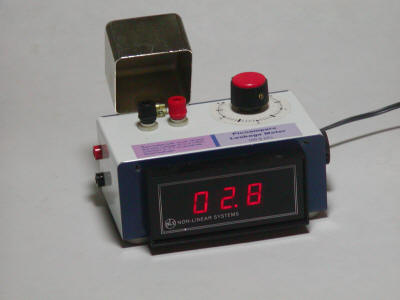
Here is a simple two-terminal picoampere leakage tester for testing diodes, JFETs and other semiconductors. The tester applies a variable voltage (0 to -4 volts) to one terminal of the component and measures the resulting current flowing into the other terminal. The 3-digit meter reads to 99.9 pA and an external meter may be connected for greater sensitivity (pin jacks on left side of case). (The digital meter is set for "200 mV" full scale with the decimal hard wired on.) A hinged cover is included to shield the component under test.
The op-amp may be just about any type but make sure to add any compensation network recommended by the manufacturer for unity gain. Internally compensated op-amps do not need additional components. My op-amp is an old CA3078 which requires compensation and a bias resistor but those components are not shown. The PN4117A is a very low leakage JFET and substitutions should have similar specs. The 462 k and 36.5 k resistors were chosen to center the zero pot and one of these values may need to be changed if the meter won't zero.
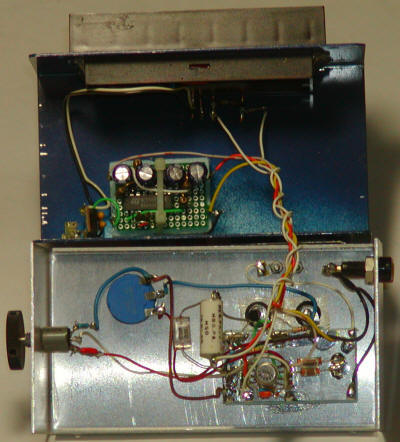
The digital meter is powered by a 5 volt, three-terminal regulator seen in the lower-left corner of the blue half of the chassis. This 5 volts also powers a voltage converter circuit that generates the +9 volts and -4 volts. Ground the power connection for the meter at the regulator and connect the negative input for the meter to the circuit ground near the op-amp. The 1 gigohm resistor will be hard to find, unfortunately. Make sure to use a very low leakage 330pF across it, perhaps a polystyrene type. I used an old glass capacitor made by Corning many years ago. If you look closely at the bottom side of the test terminals, you can see a piece of Teflon tape. I put this tape on both sides, trimmed neatly where it shows, to enhance the insulation properties of the binding posts. It might be overkill since the circuit has an arbitrary zero which you adjust before every measurement. The FET is hard to see; it is the black spot directly above the back side of the leftmost test terminal. I didn't use the 10k resistor in the gate and just connected the gate directly to the terminal. You can leave out the 10k, too, but be prepared to replace the JFET if you touch a voltage source to the test terminal! Do not connect the gate or 10k resistor to any sort of other post or PCB; keep them floating in the air connected only to the test terminal. The large resistor and capacitor should be similarly floating. Nothing should touch that connection, including any of the wiring.
Operation is simple. Turn on the device with the cover closed and let it settle for a bit. Adjust the zero pot until the meter reads near zero. A slightly positive reading is fine if your meter doesn't read negative voltages. Open the cover and install the part to be tested. Close the cover and wait for the meter to settle again. The test voltage may now be set but the meter will need to settle after every change; it's pretty sensitive! An external meter may be attached for even more resolution or you may choose to add a range switch. I find that a multi-digit bench meter is easier to use since it gives good sensitivity without overloading. I have successfully used a Teflon transistor socket to facilitate the testing of JFETs.