|
|||||||||
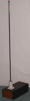 |
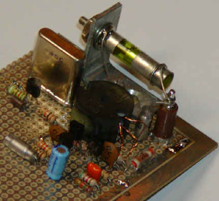
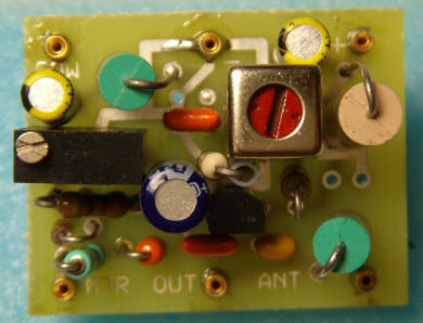
Original AM Micropower TransmitterThe picture to the left is a high quality radio transmitter for the A.M. broadcast band. The transmitter legally operates with "micro-power" and will not set any distance records but, unlike simpler designs, the frequency stays put and the fidelity is excellent. Although the schematic looks somewhat complex, the circuitry is easy to build and adjust for experimenters with a little "tweaking" experience. A simple output meter confirms proper signal level and checks antenna tuning while "on the air". Add an audio mixer, tape recorder, and perhaps a CD player and have a near-professional micro-power station.
|
||||||||
Most values are not critical but a few choices must be made carefully for best results. The output tank is tuned to the crystal frequency by selecting the values from the chart above. For example, for a 1 MHz transmitter, the chart indicates 500 pf and 35 uh. A 33uH and 550pF (470 + 82, perhaps) would be a good start. This chart assumes that a 220 pf capacitor is already connected between the collector and base of the output transistor as indicated in the schematic so the indicated capacitance is in addition to the 220 pf. A variable inductor or capacitor will allow the tank to be fine-tuned for the maximum meter reading with no antenna connected (a few volts with a 10 megohm voltmeter or about 50 microamps with a current meter). After the antenna is connected, the loading inductor in series with the antenna is selected for the minimum meter reading (best antenna loading). (A 3 foot antenna will need about 820 uH for a 1.6 MHz output frequency.) Longer antennas or higher frequencies need less inductance and shorter antennas or lower frequencies will need more. The meter reading should drop by more than half with a reasonably good antenna but the reading can be ignored if sufficient transmit range is achieved. The antenna, which is short relative to the wavelength, is hard to match well because it has a very low radiation resistance in series with a very small capacitor. (The power dissipated in the radiation resistance is the power that is transmitted.) The loading coil helps to resonate out some of the series capacity resulting in more antenna current and thus more radiated power. Some retuning of the tank may be desirable when the loading coil value is changed. A remote radio playing back through a baby monitor or walkie-talkie makes a good signal quality monitor for antenna tuning and positioning.
Note: The antenna in the picture above is just a short metal rod from an old fireplace screen stuck through an important-looking insulator strictly for appearance. It's really too short for optimum range. The 470 ohm resistor across the tank controls the Q when the antenna is short. You might be able to increase or even eliminate that resistor if your antenna and ground system are good enough. Try increasing the value, listening for distortion in a nearby radio.
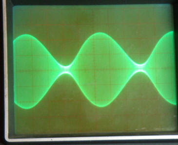
The crystal can be practically any surplus crystal with a fundamental frequency between 530 kHz and 1.7 MHz in 10 kHz increments but the higher frequencies work best. Choose a crystal frequency away from strong local stations at or above 800 kHz for best transmit range. Proper operation of the oscillator may be verified by probing the junction of the two 1000 pf capacitors with a high impedance oscilloscope probe connected to a scope or frequency counter. Full modulation is achieved by applying about 2 volts peak-to-peak to the base of the current source transistor in the differential amplifier. The modulation voltage varies the current in the diff. amp. away from the nominal 20 ma. setpoint and this modulated current is converted to a clean, high voltage sinewave by the output tuning circuit. The modulated signal may be observed with an oscilloscope connected to the antenna terminal if desired.
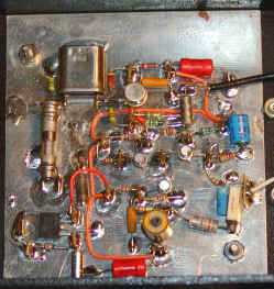
The photo above shows a prototype built with metal transistors (just for looks!) and with a few additions like the variable capacitor in series with the crystal for fine tuning and the variable inductor in the collector of the output transistor. Circuit construction is mostly non-critical but a few points should be observed. Ground-plane is not mandatory but it helps control parasitic feedback elements when less than perfect layout techniques are used. The two capacitors across the base-collector leads of the diff-amp transistors should have short leads. Bypass the 15 volt supply well, perhaps with additional 1 uF capacitors not shown in the schematic. The 100 ohm emitter resistor in the modulator may be bypassed with a 22 ohm resistor in series with a 470 uf capacitor to increase the modulation sensitivity to about 1 volt peak-to-peak which is typical of many sources. Eliminating the 22 ohm resistor will increase sensitivity to under 100 mv but the linearity will suffer somewhat.
An amplifying audio mixer may be added as shown in fig. 2 if more than one audio source is to be used. The gain resistor might be near 2.8k for typical 300 mv sources or considerably higher for lower level sources. If the signal level is different for each source then vary the 600 ohm resistors to compensate. A larger resistor will reduce the gain. Set the main gain resistor for the weakest source then increase the 600 ohm resistors in the other channels for the proper balance. A fancy mixer panel could be constructed with potentiometers in place of the resistors. Remember that some op-amps are not sufficiently fast to amplify high fidelity audio. For simplicity, choose an internally-compensated audio op-amp such as the LM833. Since the LM833 is a dual op-amp the second amp could be used as a separate pre-amp for a microphone or other low-level sources using the same schematic as the mixer. The output of this amp simply feeds one of the mixer source inputs.
![]()
Applications:
A continuous-loop tape could give sales information to passing cars. Place a sign that says, "tune to xxxAM for information," next to the house or car that is for sale. | |
Transmit special seasonal music at Christmas or Halloween to enhance your decorations. (Use a similar sign.) | |
Transmit a cassette player or other audio source to the car radio for better sound. | |
Make a pair of toy AM band two-way radios by adding inexpensive AM radios. Or talk between cars on a trip using the car radio for reception. | |
Make a baby monitor that works with any AM receiver. | |
Transmit control tones to a number of cheap AM receivers for unusual remote control applications. | |
Build a fully functional radio station for the kids - complete with vu meters, slide faders, and an "on the air" light. |
Besides making a nice general purpose radio transmitter the Personal Radio Station is suitable for some nice practical jokes:
Hide the transmitter with a cassette tape player in your personal effects as you ride in the back seat of a friend's car. (Leave out the meter circuit to keep the size down.) Ask your friend to tune in that new radio station - since your transmitter is crystal controlled it will be at the right place on the dial. What your victim hears is up to you. The circuit will work reasonably well with a single 9 volt battery instead of 15 volts. How about a less than desirable school lunch menu for the kids. Or, if you are younger, an unexpected school closing for the day. (I didn't really suggest that one, did I?) A news announcement of your marriage proposal will get results. Local news personalities will probably be delighted to help make a tape.
![]()
The Law
Part 15 of Title 47 of the Federal Code of Regulations addresses the construction of homemade AM band transmitters. The three most germane paragraphs follow:
§ 15.5 (General conditions of operation)
(a) Persons operating intentional or unintentional radiators shall not be deemed to have any vested or recognizable right to continued use of any given frequency by virtue of prior registration or certification of equipment, or for power line carrier systems, on the basis of prior notification of use pursuant to § 90- 63(g) of this chapter.
(b) Operation of an intentional, unintentional, or incidental radiator is subject to the conditions that no harmful interference is caused and that interference must be accepted that may be caused by the operation of an authorized radio station, by an other intentional or unintentional radiators by industrial, scientific and medical
(ISM) equipment, or by an incidental radiator.
(c) The operator of a radio frequency device shall be required to cease operating the device upon notification by a Commission representative that the device is causing harmful interference. Operation shall not resume until the condition causing the harmful interference has been corrected.
(d) Intentional radiators that produce Class B emissions (damped wave) are prohibited.
§ 15.23 Home-built devices.
(a) Equipment authorization is not required for devices that are not marketed, are not
constructed from a kit, and are built in quantities of five or less for personal use.
(b) It is recognized that the individual builder of home-built equipment may not possess
the means to perform the measurements for determining compliance with the regulations. In
this case, the builder is expected to employ good engineering practices to meet the
specified technical standards to the greatest extent practicable. The provisions of §
15.5 apply to this equipment.
§ 15.219 Operation in the band 510-1705 kHz.
(a) The total input power to the final radio frequency stage (exclusive of filament or
heater power) shall not exceed 100\milliwatts.
(b) The total length of the transmission line, antenna and ground lead (if used) shall not
exceed 3 meters.
(c) All emissions below 510 kHz or above 1705 kHz shall be attenuated at least 20 dB below
the level of the unmodulated carrier. Determination of compliance with the 20 dB
attenuation specification may be based on measurements at the intentional radiator's
antenna output terminal unless the intentional radiator uses a permanently attached
antenna, in which case compliance shall be demonstrated by measuring the radiated
emissions.
![]()
In this circuit, the final radio frequency stage is the transistor connected to the output tank. This transistor conducts one-half of the bias current flowing through the modulator transistor which is set to 20 ma in the circuit as shown. This current may be determined by measuring the voltage across the 100 ohm resistor. The output transistor drops about two-thirds of the power supply voltage which is 10 volts with the 15 volt supply. The power dissipated in the output stage is therefore 10 ma times 10 volts which is the legal limit of 100 mw. An antenna 9.8 feet long is the legal limit and is more than adequate if a proper loading choke is selected. In fact, an antenna only a few feet long is more manageable and may be adequate in many applications. Harmonic content of the circuit as shown was measured at the output terminal to be 27 dB below the carrier when tested at 1.6 MHz. If the tank values are selected near the values suggested by the chart, similar performance should be achieved. The connection of a properly loaded antenna will further filter the radiated signal so the device should be well inside the technical requirements.
Copyright, 1995-2002
Charles Wenzel
![]()
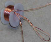
The following circuit is an improved version of the transmitter above. It features a high Q pot core autotransformer that provides a very high voltage to the antenna, greatly improving the range and an improved crystal oscillator section. (Also see phono oscillator for a tunable version.)
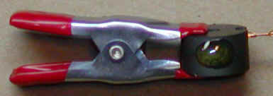
The pot core is an 1811 size high-Q ferrite core with an AL of 250nH/T2 . Two complete turns are wound on the bobbin, a loop is brought out for the tap, and 28 more turns are wound to complete the coil. Notice the knot in one end of the wire to help identify the ends after assembly. The bobbin is inserted in the core halves, the core halves are held together with a weak clamp (a strong clamp can break the core), and a couple of drops of epoxy or hot melt glue are applied to the outside of the core halves. Do not get glue on the faces of the core, the halves must be held tightly together BEFORE glue is applied.
The transformer Q combined with the turns ratio is selected to give high antenna voltage without clipping on the peaks of the modulation and without excessively limiting the bandwidth of the transmitted signal. The output tuning capacitor is adjusted for the maximum field strength and will be near 20 pF at the top end of the band and near 80pF at 1 MHz. The diode/meter circuit in the first design may be connected to the collector of this new design but the tuner is adjusted for the maximum meter reading.
The prototype is built on a piece of Vectorboard with a nice multi-turn trimmer for tuning the antenna. Longer antennas or antennas that have more capacitance may require less inductance and a few turns may be removed from the pot core.
If you prefer to have a tunable transmitter, consider the oscillator circuit below (second schematic). The AM radio oscillator coil will give excellent stability. Simply connect the output directly to the base of the leftmost NPN in the differential amplifier and adjust the 500 ohm potentiometer to get about 1 or 2 volts on the collector of the oscillator. The circuit will work fine as-is at 15 volts but raising the emitter resistor from 470 ohms to 1k will save a little power.
![]()
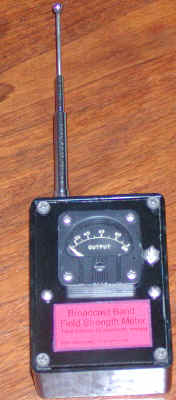
Here is a simple field strength meter that is helpful when tuning the output stage:
The circuit draws less than 10 uA with no signal so no switch is required. The variable capacitor is adjusted to tune the meter to the desired frequency by adjusting for the highest meter reading when held near the transmitter's antenna. If the meter reaches full scale during tuning or use, move the meter further from the antenna. (As you peak up a transmitter, you may need to move the meter several times to keep it on scale.) The MPSA18 may be replaced by other high gain NPN transistors, if desired. This meter has an "expanded scale" in that it goes from a zero reading to full scale over a fairly small signal level change making fine tuning easy.
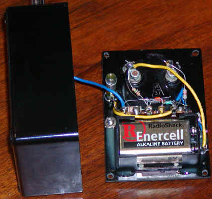
Point-to-point wiring is fine for this low frequency circuit. Remember, the meter DOES draw current when there is a meter reading above zero so don't leave it near the transmitter for long periods of time if you value you battery!
![]()
Note about part 15 AM band transmitters:
You can do better than the above circuits when going for "all out" range. With a Q of 200 at 1.6 MHz, the audio bandwidth will be 4 kHz and a simple 3 meter whip setup would need a total resistive loss of about 27 ohms to have the desired Q (Q = wL/R). That's really low even for a 3 meter whip with a good loading coil mounted above an excellent ground plane. Adding capacitance to the top of the antenna in the form of a "top hat" makes the loading coil lower in inductance and loss, but the big battle will be with ground losses. In most every situation, the ground loss with a proper antenna will be sufficiently high to give the transmitter plenty of loading and bandwidth and the battle is to get as much current to flow in that resistance as possible while consuming the legal 100 mW. Buried ground radials or some other sort of ground plane is hard to beat for getting the most range. Instead of driving the antenna system with the circuit above, use an output circuit something like that used in the Lowfer Transmitter, basically a low resistance square wave driving a very high Q loading coil that tunes the antenna. See how others have done this by searching the term "MedFER." For voice and music, modulate the power to the square wave generator with the audio signal. You still won't get a good quality signal to go very far. But the MedFER hobbyists can go hundreds of miles using very narrow bandwidth reception techniques (no voice or music, just the carrier and perhaps very slow Morse code or other encoding of an ID). The few extra dB that all this effort produces can make the difference between detecting or not detecting the signal.
So, the above circuits do not represent the absolute optimum setup for maximum legal signal strength but they are closer than some think! For example, some people object to the 470 ohm resistor across the output coil in the first circuit on the grounds that it "wastes" power that could have been transmitted. True, if you antenna system is up to the job - most aren't. Although another type of matching might give a better output, virtually all of the power is going to be wasted, anyway. A "matching network" that can provide the required loading when connected to a legal antenna without any resistors and gives a good quality signal must be lossy. You just can't see the resistor. Otherwise, the Q will be so high that the audio bandwidth is impacted and the signals sound "muffled."
In order to get the bandwidth high enough for music, the natural Q of the typical short antenna must be lowered by a factor of several hundred and there goes all that precious power! Basically, you want the highest possible voltage on the antenna but that value is limited by the maximum acceptable Q (lowest tolerable bandwidth) and the allowed power. One way or the other, you must include resistive losses. These circuits (especially the first) "over do it" a bit to make them more forgiving. (A poorly tuned matching network or a short antenna may not exhibit the necessary loss causing the modulation to be distorted.)
![]()
Richard de los Santos
![]()
A "phono oscillator" is a simple, short-range AM band transmitter that was typically used to send the signal from a phonograph to a nearby radio, eliminating the need for an amplifier and speaker. This version uses only one transistor and can be tuned to any desired frequency near the top of the AM band. Fidelity is surprisingly good considering the simplicity and is suitable for transmitting "Golden Age of Radio" type shows to a restored tube set.

Instead of a crystal, this transmitter uses an oscillator coil intended for AM radios. These coils usually have a red adjustor and the winding with the highest resistance is used, leaving the other pins unconnected. The 33 pF places the optimum frequency near the top of the dial but it may be increased to 68 pF for operation near 1 MHz. The input and collector chokes are millihenry values (not microhenry). The transistor isn't critical and just about any NPN small-signal type will work fine. The collector output may be used to drive other circuits (like the differential amplifier in the previous circuit in place of the crystal oscillator) but it may be desirable to add a few thousand ohms in series to prevent excessive loading of the oscillator (see circuit below). The Ant. output has a loading coil in series to achieve a much higher voltage on a few meter length of wire but you won't get much range from this circuit.
My circuit board was designed to plug into those white prototyping boards. If you count parts and find one is missing, it's on the back due to a slight layout boo-boo.
Tune up is easiest with an oscilloscope. First tune the oscillator to the desired frequency with no modulation. Then apply a 1 kHz, 500 mV p-p sinewave to the input and adjust the 500 ohm potentiometer for the most symmetrical waveform. Looking at the Ant terminal with a few feet of wire may give the best view of the actual waveform since the audio signal can make the RF look a bit distorted at the collector even though it isn't. Simply placing a scope probe near the antenna is usually sufficient. Play with the input level and 500 ohm pot to get the best waveform but keep the input a little short of 100% modulation, perhaps 90%. The1N914 (or similar diode), 0.1uF capacitor and 1 megohm resistor allow a digital voltmeter to monitor the oscillator level. The best operating point will produce a meter reading near 0.7 volts with no modulation. These parts may be left out if the circuit is to be adjusted with a 'scope.
A simple oscillator to replace the crystal oscillator in the first project above may be constructed as follows:
The circuit will operate on 15 volts without modification but the 470 ohm emitter resistor may be increased to save a little power.
![]()
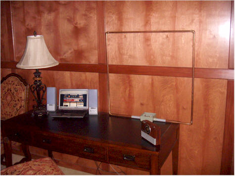
It may come to pass that AM radio stations begin to disappear, switch to a music format, or even worse, switch to local programming. : ) The process will probably be slow and those interesting talk programs will be available for some time over the Internet. For those caught in such a state of Limbo, the Unfair Radio Transmitter comes to the rescue. The Unfair Radio Transmitter is a personal radio station that broadcasts an Internet audio feed throughout the house so that those AM radios scattered about remain useful. This is a great approach for covering a typical home and lot with a good quality signal.
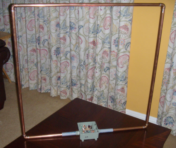
Those who have experimented with electric field transmitters like those above have probably discovered that they only work well when the antenna is free and clear and there is little solid matter between the transmitter and receiver. The electric field is easily "shorted out" by even slightly conductive materials. In contrast, this loop transmitter generates a magnetic field that can cut right through the thickest walls. I live in an old rock home filled with concrete and reinforcing wire mesh and this transmitter's signal can be easily picked up in the bomb shelter at the opposite end of the long house. I'm sure it can be received in the cave next door! (Freely propagating EM signals from a legal transmitter are quite weak and sound pretty noisy but the "near-field" reception of the magnetic or electric field can be quite good.)
The circuit is nearly identical to the ones above with the exception of the loop components and a few of the bias resistors. The dimensions of the loop were chosen to adhere to the most strict interpretation of the FCC rules regarding antenna length. The simple square design yields an inductance of 2 uH when constructed with 1/2" copper tubing. That inductance determines all the rest of the antenna values. First, the series combination of the two capacitors (shown as 8000 pF) must resonate with the inductance at the selected frequency. The Q must be kept down to about 225 for adequate bandwidth for typical talk radio programming (even less for music). That Q value means that the losses in the antenna circuit must be near 4,000 ohms, shunt. The 10 k resistor shown is representative of a value that might be added to bring the Q down to the right value. Don't worry about the "loss" of signal power; it is unavoidable if the proper bandwidth is to be maintained. Tuning and selection of loading components will be discussed below. It turns out that the maximum voltage swing that can be achieved at this Q with a class-A driver is about 70 volts p-p at full modulation, so a capacitive tap is used to cut that voltage in half, just right for a 24 volt power supply. 35 volts p-p swing on the collector will bring the collector voltage down to about 6.5 volts, leaving about 4.5 volts from collector to emitter.
The 180 ohm emitter resistor sets the current in the output stage to about 10 mA or 5 mA per side. The stead-state voltage across the output transistor is about 20 volts so the power in that last transistor is 20 V x 5 mA = 100 mW, the legal limit. You can't simply lower the 180 ohm resistor for more power, the voltage swing will be too big.
One nice thing about this circuit is that it operates at a fairly low impedance. A 10X scope probe may be directly connected to the loop to observe the voltage:
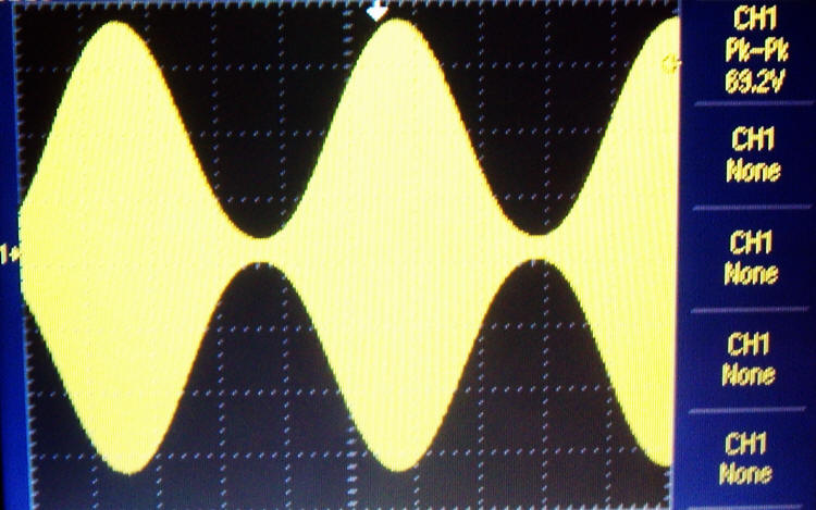
This image was taken with an oscilloscope probe connected directly to the loop. The 22 uH choke that provides bias to the collector of the output transistor may be a higher value, typically 100 uH; I just happened to have a large 22 uH at hand and the value isn't critical. The low 22 uH value just reduces the effective capacitance of the capacitors slightly, perhaps 5 %. The two series 8000 pF capacitors are selected to resonate the loop at the desired frequency. Tack in candidate values then add a trimmer capacitor across the coil to see how you did. You can also leave a trimmer capacitor in the circuit, if desired. I discovered that my capacitors were slightly too big so I simply paralleled a small 100 uH molded choke to lower the inductance a bit. It turned out that this inductor had just the right amount of loss to eliminate the need for a shunt resistor. But, earlier, I used a trimmer capacitor and about 10 k to get the proper Q. If the loop is not sufficiently loaded, the sinewave will begin to flatten on the top and bottom at full modulation, at about 70 volts p-p. You can increase the Q (by reducing the loading of the coil) to get more swing but your signal will sound muffled. Just add a resistor across the coil until the waveform looks like the one above. The voltage above suggests that the circulating current in the coil is over 3 amps!
I found it handy to have a trimmer capacitor across the coil for peaking with my field strength meter when prototyping. Once everything is working perfectly, the capacitor may be replaced with a fixed value. I found that sticking my hand in the loop didn't detune the circuit much so a trimmer capacitor may be mounted right across the coil and tweaked by hand at the very end. The scope probe does detune the loop slightly but a light adjustment of the trimmer brings the amplitude back to the peak.
The circuit is mounted in a standard plastic conduit box but the interface to the loop was more difficult than might be obvious. The copper tubing doesn't really fit inside the PVC tubing. I heated the PVC until it was soft, then shoved it on the precise distance I needed. I then had to sand down the end of the PVC pipe so that it would fit into the box again. The end result is a very snug fit, but it would be a lot easier to just use all PVC tubing and run some heavy wire or braid through the inside. Perhaps a piece of RG58 inside the PVC would be about right. The smaller diameter of the conductor will increase the inductance a bit so expect lower value capacitors for resonance.
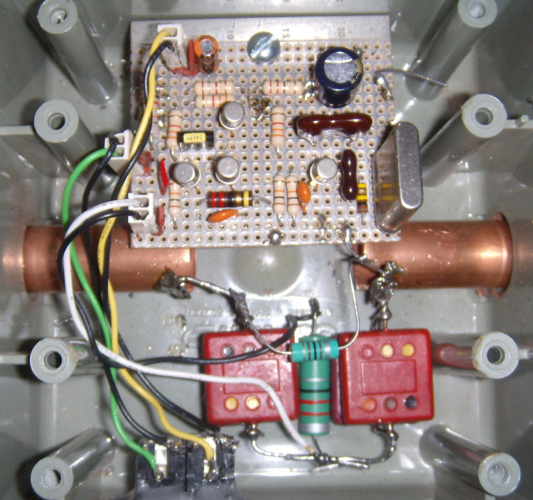
In order to solder to the ends of the pipe, I cut little tabs with an high-speed abrasive wheel. They're bent toward the bottom of the photo. Notice the 100 uH choke that tuned my final design perfectly. That was replaced by a resistor in parallel with a 365 pF trimmer capacitor at one time. The two capacitors are made by paralleling two old-style mica capacitors for a value near 9000 pF. Stay with high-quality capacitors like mica, glass, porcelain, Teflon, and NPO ceramic. Ordinary ceramic is a bit lossy but those losses might be just about what you need to set the Q. If your capacitors are too lossy, you will be able to get a peak but the voltage will be low. The large 22 uH could have been another 100 uH or higher. I used some old 2N718A metal transistors instead of the 2N4401 but most small-signal transistors should work fine. Using two pin connectors for the power, audio, and antenna make it a lot easier to make changes to the board. Notice the piece of wire soldered to the ground plane in the top-right corner of the board. That is for connecting the scope and voltmeters. Not shown is the 24 volt molded power supply and the cable that runs to the computer speaker jack.
The audio gain is a bit high to accommodate wimpy sources but the 22 ohm in the emitter of the bottom transistor is low enough to start causing distortion. If your computer can drive the circuit readily, increase that value until you are running the volume on the laptop near full. There are freeware programs for generating a sine wave that are great for looking at the modulation level.
This was a fairly trouble-free project and it works great but let me know if you have any problems. (charles@wenzel.com)
FYI: The name "Unfair Radio Transmitter" is a play on the "Fairness Doctrine", intended as humor. Well, I think it's funny.
![]()