Make sure to see the several readers' versions
Also see the new Sferics Detector
The following circuit is an improved version of my original Lightning Detector designed to run on a 5 volt supply. The new circuit features a superior RF section with a single resonance near 300kHz and plenty of sensitivity. The potentiometer was eliminated; simply adjusting the length of the telescopic antenna will give the desired sensitivity. The circuit supply voltage was increased to 5 volts to allow the use of commonly available molded power supplies instead of batteries. Another not-so-obvious feature is that I have plenty of the inductors! (For inductors email charles@wenzel.com.)
The basic receiver is shown below. The antenna is a telescopic antenna that extends to two or three feet, the length is not critical. A high-value resistor (270k) is connected from the antenna to ground to control the Q and this value may be lowered if the circuit seems unstable but too low a value will destroy the sensitivity. The 10 mH and 1 mH ( not uH) chokes are molded types but most moderately high-Q inductors will work fine and the rest of the parts are run-of-the-mill and not particularly critical. The transistors are all general-purpose types.
Theory of operation:
The antenna, 10 pF capacitor, and the two inductors form a resonant tank at about 300 kHz, a good frequency for receiving energy from lightning. The two series inductors act as a matching network, feeding Q1 with a lower impedance version of the signal received by the antenna. The 270k resistor lowers the Q of the resonant tank to prevent oscillation. Q1 amplifies the 300 kHz bursts and applies the larger signal to the base of a PNP transistor that forms a monostable "flasher" circuit with the last NPN transistor. When the RF signal pulls the PNP base voltage below the voltage on the 10 uF capacitor (plus about 0.6 volts) the PNP turns on, turning on the NPN. Since the NPN is connected to the base of the PNP through the 82 k resistor, the PNP turns on even harder. This regenerative action causes the circuit to turn on quickly and fully, pulling the "pulses" line to nearly zero volts. The circuit stays on until the 10 uF capacitor discharges at which point a similar reverse regenerative action causes the circuit to quickly switch off. The capacitor then quickly charges through the 1k resistor (in one of the lamp circuit options) and the diode and is ready for another pulse.
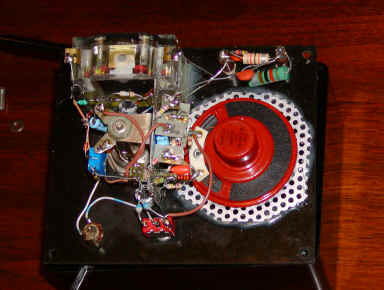
The prototype is built into a phenolic box using point-to-point wiring. The power switch is a single pole, double throw type with a center-off position. The power supply is connected to the center terminal and the speaker is connected to one of the outer terminals. Both of the outer terminals are also connected to the other circuitry through a couple of silicon diodes, one from each terminal. One diode keeps the speaker from getting power in the 'speaker off' position and the other diode is simply there so that the circuitry sees the same voltage in both 'on' positions. Alternately, a switch could be added in series with the speaker to turn it off. After one storm, you will add the switch if you don't include it at first!
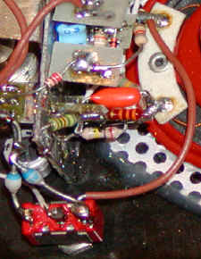 |
The diodes can be seen in the close-up of the power switch. Alternately, a ordinary single pole, single throw switch could be used with another switch in series with the brown wire to disconnect the speaker when the constant crackle becomes too annoying! |
The basic circuit above is combined with any of the following circuits to complete the lightning detector. The prototype used the 5 volt lamp driver, meter circuit, and speaker circuit.
The second circuit will drive higher current lamps, up to 500mA. Flashlight bulbs make a bright flash.
The meter sensitivity may be altered by changing the 5.1k resistor.
No volume control is included but the sound level is not particularly loud.
Choose any or all of the above circuits and connect them across the indicated terminals on the basic receiver. An alarm, buzzer, or other load may be activated when the lightning activity exceeds a preset level using the following circuit:

A different op-amp or comparator may be used, as long as it is "ground sensing". Look for single-supply types for substitutes. The '339 requires a pull-up resistor on the output but op-amps will not require this part (the 1k resistor). The power supply may be the same 5 volt supply or a different voltage as long as the voltage is within the operating range of the op-amp or comparator. The VMOS transistor may be any type sufficient for driving the load. A VN10KM is a typical part for lower current loads. Add a power switch in series with the load, if desired.
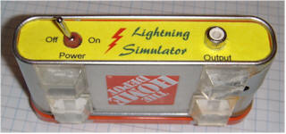
This little simulator generates short pulses at a few Hz rate and is helpful in designing and testing lightning detector circuits like the one at the top of the page. The output is connected to a shielded audio cable with an RCA type connector. The other end of the cable is connected to the antenna of the lightning detector through a 10 pF capacitor (not shown). The shield of the audio cable is connected to the detector's ground. The 10 pF allows the lightning detector's tuned circuit to ring and the amplitude of the ring may be observed on the collector of Q1 (see schematic at the top of the page).
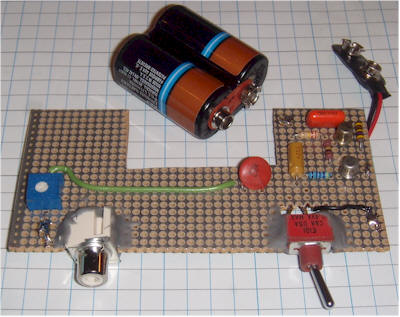
The circuit is built into a Home Depot gift certificate can. The circuit board slides into two card guides glued to the ends of the can. Any type of construction will probably work fine, but a metal can is recommended to keep the pulses "contained."
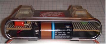
Parts aren't critical. The actual unit uses metal can transistors, but just about any small-signal types should be fine. The battery is a 6 volt camera type, but a 9 volt rectangular will also work. The pulses are short and low frequency, so it may be hard to see them on an analog oscilloscope. They can be heard if the output is connected to a bench audio amplifier.
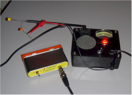
Note the 10 pF in series with the antenna connection.
The following two circuits may be improved by modifying the antenna/RF section to look like the new circuit above ( the 10mHy and 1 mHy chokes, the 10pF capacitor, and the 270k resistor). This modification removes a resonance in the lower part of the broadcast band that might make the detector susceptible to interference. The resulting circuits will work great and may be adjusted for extreme sensitivity.
Egor! Come quick! A storm approaches!
Here is a LF receiver tuned to 300 kHz designed to detect the crackle of approaching lightning. A bright lamp flashes in synchrony with the lightning bolts indicating the proximity and intensity of the storm. Figure 1 shows the simple receiver which consists of a tuned amplifier driving a modified flasher circuit. The flasher is biased to not flash until a burst of RF energy, amplified by the first 2N4401, is applied to the base of the 2N4403. The receiver standby current is about 350 microamps which is nothing at all to a couple of D cells, hardly denting the shelf life. Of course, the stormier it gets, the shorter the battery life.
For best effect, mount the lamp in an old-fashioned holder with an extra-large colored glass lens. Or construct your own fixture with a plate of textured colored glass behind a panel painted with black-crackle paint. Watch a few old science fiction movies for other ideas.
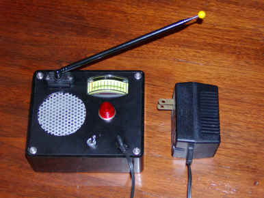
A totally different approach is to mount the circuit in an empty glass jar with the antenna and bulb protruding through the top. (A malted-milk jar has a nice, red plastic lid which is easy to work and looks good.) Use a pin jack for the antenna. The gadget looks quite home-made but fascinating.
Boat owners may wish to replace the lamp with a 3-volt beeper to provide an early warning of approaching bad weather. Choose one of those unbreakable clear plastic jars like the large jars of coffee creamer. A little silicone rubber will seal the antenna hole in the lid of the jar. Use a longer antenna for increased sensitivity since there are few electrical noise sources on the lake.
Tune-up is simple: adjust the potentiometer until the regular flashing just stops. (Use a multi-turn trimmer.) When properly adjusted, the lamp will occasionally flash when large motors or appliances switch on and off and an approaching storm will give quite a show. Obviously, tune-up is a bit more difficult during stormy weather. Adjust the pot with no antenna if lightning is nearby. Tune an AM radio to the bottom of the dial to monitor the pulses that the lightning detector is receiving.
This lightning detector is not so sensitive that it will flash with every crackle heard on the radio but will only flash when storms are nearby. Increased sensitivity may be achieved by increasing the antenna length. The experienced experimenter may wish to add another gain stage after the first by duplicating the RF amplifier circuitry including capacitor coupling with the addition of a 47 ohm emitter resistor to reduce the gain somewhat. This additional gain can cause stability problems if the layout is poor so novices are advised to use a longer antenna or adjust the sensitivity potentiometer more delicately instead! (When operating properly, the additional gain makes the pot adjustment much less critical.)

Theory of Operation:
Lightning flashes generate a broad spectrum of radio frequencies with especially intense emissions in the VLF band. This receiver is designed to pick up a band near 300kHz which is fairly empty except for lightning static. These radio "crackles" are picked up by the antenna with the help of the 10 millihenry choke. Short antennas (short compared to the wavelength, that is) behave as though a very tiny capacitor is connected in series and this choke resonates with this capacitor allowing current to flow into the receiver. The 330 uH and 680 pF form a tuned circuit at 300 kHz and the 0.01 uF couples this tank into the base of the first transistor amplifier. The amplified radio signal on the collector is coupled into the base of the second transistor which is part of a lamp flasher circuit. The flasher is biased such that it doesn't flash (by careful adjustment of the pot) until a radio burst pulls the base of the 2N4403 down. Positive feedback causes the flasher to quickly turn full on until the 100 uF capacitor discharges giving a good lamp flash. The circuit quickly resets by charging the 100 uF capacitor through the 1N914.
Transistor substitutions are fine. Most modern small-signal transistors will work well in the circuit including 2N3904 (NPN) and 2N3906 (PNP). Avoid high frequency "RF" transistors since unwanted oscillations may result.
Note: A reader, Bob Radmore (N2PWP) has written an article featuring this lightning detector for the April, 2002 issue of QST, ARRL's monthly membership journal.
Inspired by this season's first thunderstorm here is another experimental version of the lightning detector that features lower battery drain and additional functions:
The basic receiver is similar to the first version except that the RF amplifier is a bit starved for current which saves power and also provides demodulation for listening to the lightning crackles. The flasher portion uses much less current but only provides a low current positive pulse which needs further conditioning for most purposes. When idle this new circuit draws only about 100 uA so applications using smaller batteries are practical. One or more of the following options are connected to the receiver to complete the detector:
This LED driver consumes much less current than the previous design but the light output is less.
The audio amplifier connects to the collector of Q1 and allows the user to listen to the received signal. The volume is not great but an optional volume control may be added by replacing Q1's 10k collector resistor with a 10k potentiometer with the wiper connecting to the 10k on the input of the amplifier. A power switch is included since this amplifier will draw several milliamps. Adjust the resistor from the cathode to reference for 5 to 20 mA DC power consumption.
The averaging meter shows a fairly steady reading that is proportional to the lightning activity. A DC output is provided for driving a comparator for alarms, automatic controls, etc.:
The alarm comparator is used to drive a buzzer or other type alarm, a motor, relay, or other heavy electrical load. A separate power supply provides power to the comparator and load. The 10k input resistor connects to the output of the averaging meter circuit and the 10 megohm provides some hysterisis for quick switching. The 50k pot is adjusted for the desired trip point. Any n-channel VMOS power transistor will work as long as it is rated for the load current. An LM358 op-amp or other ground-sensing op-amp may be substituted for the comparator.
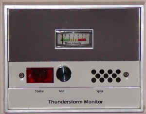
All of the options may be included in one unit. The photo below is my detector in my living room. It is built into an abandoned control panel for an electronic air filter and includes the incandescent lamp, meter and speaker options.